
In-ear angle adaptive earphone

A self-adaptive and self-adaptive adjustment technology, applied in earphone/earphone accessories, earphone manufacturing/assembly, amplifiers, etc., can solve the problems of reduced sound insulation effect, user discomfort, insufficient combination of earphones and ears, etc., to achieve enhanced Insulation effect, tightly combined effect

Active Publication Date: 2016-03-02
深圳市奥科斯数码有限公司
View PDF4 Cites 11 Cited by
  • Summary
  • Abstract
  • Description
  • Claims
  • Application Information

AI Technical Summary

Problems solved by technology

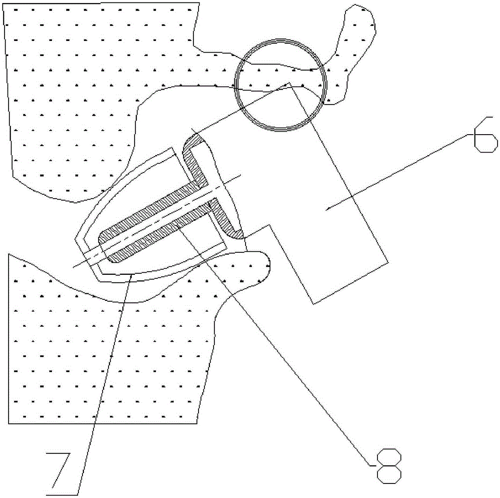
When the user puts the earphone into the ear, the sound guide tube 8 is placed in the ear canal, and the top of the shell 6 is in contact with the auricle or the entrance of the ear canal. Since the sound guide tube 8 is fixedly connected to the shell 6, the shell 6 will touch the auricle. Or the entrance of the ear canal is squeezed, the user will feel uncomfortable, and the earphone is not tightly combined with the ear after wearing it, resulting in a decrease in the sound insulation effect. At the same time, the earphone is not suitable for users with different ear types.

Method used


Image

  • In-ear angle adaptive earphone
  • In-ear angle adaptive earphone
  • In-ear angle adaptive earphone

Examples


Embodiment 1

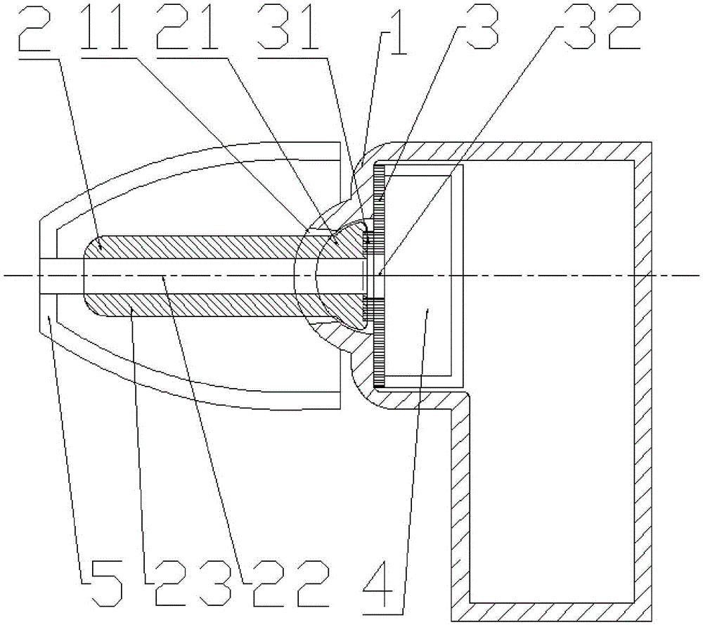
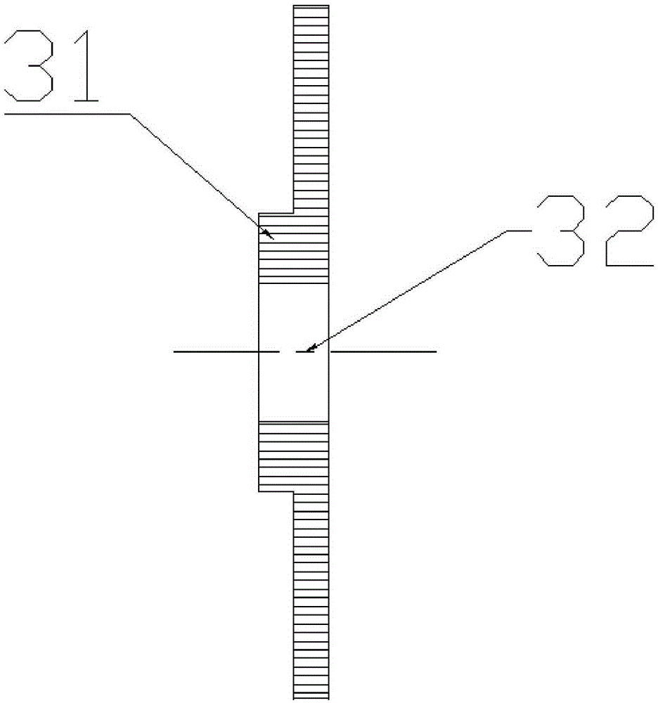
[0028] see figure 2 and 3 , which are respectively a cross-sectional view of the earphone and a cross-sectional view of the adaptive adjustment part according to Embodiment 1 of the present invention. The self-adaptive adjustment part 3 is a soft sponge sheet with a memory function, and a protrusion 31 is arranged in the middle thereof, and a sound guide hole 32 is arranged in the protrusion 31 . The sound guiding unit 2 is provided with a sound guiding channel 22 , and the sound guiding unit 2 includes a sound guiding tube 23 and a universal joint movable end 21 fixedly connected to one end of the sound guiding tube 23 . The movable end 21 of the universal joint is a hemispherical structure with an end surface and a hemispherical surface. The earphone housing 1 is provided with a housing chamber, the universal joint movable end 21 is inserted into the housing chamber of the earphone housing 1, and the hemispherical surface of the universal joint movable end is rotatably in...

Embodiment 2

[0033] see Figure 6, which is a cross-sectional view of the earphone according to Embodiment 2 of the present invention. Embodiment 2 is substantially the same as Embodiment 1, except for the following difference: the sound guide tube 230 passes through the limiting hole 110 and is affixed to the end face of the universal joint movable end 210, and the adaptive adjustment part 30 is sleeved on the On the sound guide tube 230 , at the same time, the adaptive adjustment part 30 is clamped between the inner wall of the housing cavity of the earphone housing 10 and the end surface of the universal joint movable end 210 and abuts against both. The earphone shell 10 is also provided with a shell sound guide hole 120, one end of the shell sound guide hole 120 communicates with the sound guide channel 220, the speaker 40 is arranged in the earphone shell 10 and is installed near the other end of the shell sound guide hole 120, At the same time, it is close to the sound guide channel...


PUM


Abstract

The invention relates to an in-ear angle adaptive earphone. The in-ear angle adaptive earphone includes an earphone shell, a sound guide unit and an adaptive adjustment part; one end of the sound guide unit is a connecting end and is rotatably arranged on the earphone shell; the other end of the sound guide unit is an in-ear free end; a sound guide channel which passes through the connecting end and the free end of the sound guide unit is arranged in the sound guide unit; the adaptive adjustment part is arranged between the earphone shell and the connecting end of the sound guide unit; when the sound guide unit is externally stressed and rotates relative to the earphone shell, the adaptive adjustment part abuts against the connecting end of the sound guide unit and is deformed, so that the sound guide unit can be maintained in a rotation position; and after an external force disappears, the adaptive adjustment part is rehabilitated, so that the sound guide unit can be reset to an original position. When the in-ear angle adaptive earphone of the invention is used, the sound guide tube and the earphone shell of the earphone can rotate relatively, and the sound guide tube can be automatically maintained at a certain rotation angle through the adaptive adjustment part, and therefore, the ear canal of a user will not be stressed, and the earphone can be tightly combined with the ear canal, so that a sound insulation effect can be enhanced.

Description

technical field [0001] The invention relates to an earphone, in particular to an in-ear earphone. Background technique [0002] see figure 1 , which is an in-ear earphone in the prior art. The in-ear earphone includes a shell 6, a horn, a sound guide tube 8 and a cork 7. The horn (not shown in the figure) is installed in the shell 6, and the sound source that the horn sends passes through the sound guide channel in the sound guide tube 8, and the soft plug 7 is sleeved on the sound guide tube 8. When the user puts the earphone into the ear, the sound guide tube 8 is placed in the ear canal, and the top of the shell 6 is in contact with the auricle or the entrance of the ear canal. Since the sound guide tube 8 is fixedly connected to the shell 6, the shell 6 will touch the auricle. Or the entrance of the ear canal is squeezed, the user will feel uncomfortable, and the earphone is not tightly combined with the ear after wearing it, resulting in a decrease in the sound insul...

Claims


Application Information

Patent Timeline
Patent Type & Authority Applications(China)
IPC IPC(8): H04R1/10
CPCH04R1/1058H04R2201/105
Inventor 周克明
Owner 深圳市奥科斯数码有限公司
Learn More