
Stitching process equipment automatic device

A technology of equipment automation and lamination process, which is applied in printed circuit manufacturing, electrical components, printed circuits, etc., can solve the problems of low labor efficiency and equipment efficiency, boards cannot be operated at the same time, and the degree of automation is not high, so as to reduce personnel handling , Shorten the time of target shooting and stacking, and save costs

Inactive Publication Date: 2016-03-02
JIANGSU BOMIN ELECTRONICS
View PDF4 Cites 11 Cited by
  • Summary
  • Abstract
  • Description
  • Claims
  • Application Information

AI Technical Summary

Problems solved by technology

[0002] At present, the pressing process used in the industry is mostly a single device, and it is planned in different regions and units, and cannot be interconnected.
First of all, the shooting machine works alone. The staff divides the boards into piles according to the shooting data, and manually distinguishes the expansion and contraction. The pass rate of one shot is low. The boards with different expansion and contraction need to be shot many times, and the production efficiency is low. The edging machine works. After the edging is completed, it is manually transported to the edging line for operation. After the edging is washed by the washing machine, the thickness of the board is measured, and the board is finally collected. The boards with different expansion and contraction cannot be operated at the same time.
The process from shooting to edging needs to be completed through multiple equipment operations. There are many equipments, complicated procedures, and high abnormality rate; the labor efficiency and equipment efficiency are low, and the degree of automation is not high. The beginning and end stages of each line need to be retracted manually. board work

Method used


Image

  • Stitching process equipment automatic device
  • Stitching process equipment automatic device
  • Stitching process equipment automatic device

Examples


Embodiment Construction

[0032] The technical solutions of the present invention will be described in detail below in conjunction with the accompanying drawings and preferred embodiments.

[0033] Such as figure 1 Shown is a schematic diagram of the operation flow of the traditional lamination process.

[0034] Such as figure 2 As shown, it is a schematic diagram of the operation flow of the lamination process equipment automation device disclosed in the present invention.

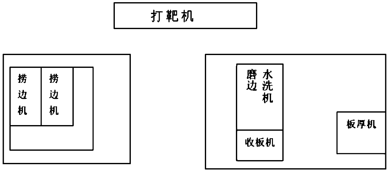
[0035] Such as image 3 It is a distribution map of the traditional lamination post-processing area. Different equipment is located in different space ranges, which wastes space, and cannot work continuously, wastes resources, and reduces production efficiency.

[0036] Such as Figure 4 It is the planning of the newly disclosed connection operation area in this city. The optimized planning of the connected operation area saves space, has a high degree of automation, is easy to operate, improves work efficiency, saves costs,...


PUM


Abstract

The invention discloses a stitching process equipment automatic device, comprising six devices: a target-shooting machine, a dragging and edging machine, a chamfering machine, a washing machine, a plate thickness measuring machine, and an automatic categorization plate collector, and characterized by comprising a: area programming: programming the area layout of each device together, and leaving no obstructs among connection; and b, employing a conveyer, a conveyor belt, a central positioning machine and a lower trigger among equipment for connection, and allowing the equipment to perform effective transmission connection work. According to the technical scheme, all works can be completed only through placing a plate by the target-shooting machine; the work which requires multiple persons and multiple processes is improved to automatic line production which can be completed by a single person, thereby reducing costs, and increasing efficiency; the stitching process equipment automatic device has a high automation degree, is easy to operate, and can improve work efficiency, reduce production abnormity and manual carrying, decrease scratch discards, and save manpower resources.

Description

technical field [0001] The invention relates to an automation device, in particular to an automation device for pressing process equipment. Background technique [0002] At present, the lamination process used in the industry is mostly a single device, which is planned in different regions and units, and cannot be interconnected. First of all, the shooting machine works alone. The staff divides the boards into piles according to the shooting data, and manually distinguishes the expansion and contraction. The pass rate of one shot is low. The boards with different expansion and contraction need to be shot many times, and the production efficiency is low. The edging machine works. After the edging is completed, it is manually transported to the edging line for operation. After the edging is washed by the washing machine, the thickness of the board is measured, and the board is finally collected. The boards with different expansion and contraction cannot be operated at the same...

Claims


Application Information

Patent Timeline
Patent Type & Authority Applications(China)
IPC IPC(8): H05K3/00
CPCH05K3/0044
Inventor 黄继茂周先文付小辉付廷昌
Owner JIANGSU BOMIN ELECTRONICS
Learn More