Adjustment base for clamping PCB

A technology of PCB board and adjustment base, applied in the direction of PCB socket, support structure installation, etc., can solve the problems of inability to adapt to different types and the size of the clamping base is not adjustable, and achieve the effect of preventing electrostatic breakdown and avoiding deformation

Active Publication Date: 2016-03-02
东莞市兴联电子科技有限公司
View PDF7 Cites 1 Cited by
  • Summary
  • Abstract
  • Description
  • Claims
  • Application Information

AI Technical Summary

Problems solved by technology

[0003] In order to solve the defects that the size of the existing clamping seat cannot be adjusted and cannot adapt to different types of PCB boards, the present invention provides a PCB board holder with adjustable size

Method used


Image

  • Adjustment base for clamping PCB
  • Adjustment base for clamping PCB
  • Adjustment base for clamping PCB

Examples


Embodiment 1

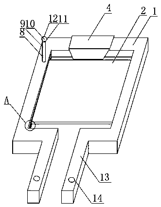
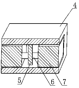
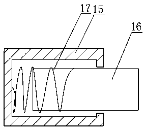
[0025] Such as figure 1 , figure 2 , image 3 , Figure 4 As shown, the adjustment base for clamping the PCB board includes the frame frame 1 and the PCB board 2 clamped in the frame frame 1; the inner wall of the frame frame 1 is provided with a groove 3, and the two ends of the PCB board 2 respectively arranged in the grooves 3 on the left and right side walls of the frame frame 1; The sliding rod 7 connected with the fixed rod 5 through the elastic member 6; the frame frame 1 is provided with a winding column 8; the elastic member 6 includes a connecting rod 15 with an end opening as a cavity structure, and is slidably arranged on the connecting rod The adjusting rod 16 in 15 and the spring 17 connecting the adjusting rod 16 and the connecting rod 15, the adjusting rod 16 is sleeved in the spring 17, one end of the spring 17 is arranged at the bottom of the connecting rod 15, and the other end is arranged on the side of the adjusting rod 16 on the wall.

[0026] In th...

Embodiment 2

[0028] In this embodiment, on the basis of Embodiment 1, the winding post 8 includes a support rod 9 and a snap ring 10 fixed on the upper end of the support rod 9 . The snap ring 10 includes a lower snap ring 11 and an upper snap ring 12 with one end hinged to the lower snap ring 11 and the other end snapped to the lower snap ring 11 . The lower snap ring 11 is fixed on the upper end of the support rod 9 .

[0029] When the lines are to be collected, the upper snap ring 12 snapped to the lower snap ring 11 is opened, and the lines on the PCB 2 are placed in the snap ring 10 for fixing, so that the lines are arranged in an orderly direction toward the set direction. The lines on the PCB board 2 are neat and beautiful, and the heat dissipation of the PCB board 2 is also beneficial.

Embodiment 3

[0031] In this embodiment, on the basis of Embodiment 1 or Embodiment 2, one end of the frame 1 is open, and further includes extensions 13 respectively arranged on both sides of the opening, and threaded holes 14 are provided at the ends of the extensions 13 . The threaded hole 14 provided at the end of the extension section 13 is used to fix the entire frame 1 on the chassis.


PUM


Abstract

The invention discloses an adjustment base for clamping a PCB. The adjustment base comprises a window-type frame and the PCB clamped in the window-type frame. The inner-side wall of the window-type frame is provided with grooves, the two ends of the PCB are respectively arranged in the grooves at the left-side wall and the right-side wall of the window-type frame; the window-type frame comprises a sleeve whose openings at two sides are of cavity structures, a dead lever arranged in the inner cavity of the sleeve and slide bars respectively connected with the fixed lever through an elastic member; the window-type frame is provided with a wrapping post; and the elastic member comprises a connecting rod whose opening at one end is of a cavity structure, an adjustment rod slidably arranged in the connecting rod and a spring connecting the adjustment rod with the connecting rod, and the adjustment rod is sleeved by the spring. According to the invention, the adjustment rod is sleeved by the spring to enable the spring to extend only along the axial direction of the adjustment rod so as to limit the spring and prevent the spring from deformation due to stretching.

Description

technical field [0001] The invention relates to an adjustment base, in particular to an adjustment base on which a PCB board is clamped. Background technique [0002] Printed circuit board (i.e. PCB board) is an important electronic component, a support for electronic components, and a provider of electrical connections for electronic components. Because of its powerful functions, it is now widely used. In the assembly process of the existing PCB circuit board, the PCB circuit board is generally fixed on the casing by means of screw fixing, that is, the PCB circuit board is generally provided with mounting holes, and the screws are embedded in the corresponding mounting holes and screwed on during assembly. Installed in the case. However, in actual use, the PCB circuit board fixed by screws is easy to be damaged due to vibration and other reasons. In order to solve this defect, a clamper is mostly used to clamp the PCB board, and then the clamper is fixed on the chassis. ...

Claims


Application Information

Patent Timeline
Patent Type & Authority Applications(China)
IPC IPC(8): H05K7/14
CPCH05K7/1424
Inventor 陈小英
Owner 东莞市兴联电子科技有限公司
Why Eureka
Try Eureka