Combined propeller cap for reducing rotating flow and hub vortex and enhancing propulsion efficiency

A propeller hub and propulsion efficiency technology, which is applied in the direction of rotating propellers and rotary propellers, can solve the problems of increasing manufacturing difficulty and increasing production costs, and achieve the effects of improving propulsion efficiency, low cost, and reducing hub vortex cavitation

Active Publication Date: 2016-03-02
KOREA INST OF OCEAN SCI & TECH
View PDF9 Cites 6 Cited by
  • Summary
  • Abstract
  • Description
  • Claims
  • Application Information

AI Technical Summary

Problems solved by technology

[0022] The present invention aims to solve the problems of the prior art as described above, so the purpose of the present invention is to provide a composite propeller hub cap for reducing the rotating flow and hub vortex and improving propulsion efficiency, in order to solve the existing The following problem of PBCF (PropellerBossCapFin), that is, the propeller hub cap is provided with a plurality of small fins (fin) to reduce hub vortex cavitation. Therefore, in order to design and manufacture fins, precision machining is required, which increases the difficulty of manufacturing and leads to production The cost increases. The composite propeller hub cap of the present invention reduces the hub vortex that occurs behind the propeller by combining the composite propeller hub cap structure of the existing contraction type (contraction type) propeller hub cap end with a diffusion type (diffusion type) propeller hub cap. Cavitation, which can be easily fabricated at a very low cost by virtue of a far simpler structure than the existing PBCF

Method used


Image

  • Combined propeller cap for reducing rotating flow and hub vortex and enhancing propulsion efficiency
  • Combined propeller cap for reducing rotating flow and hub vortex and enhancing propulsion efficiency
  • Combined propeller cap for reducing rotating flow and hub vortex and enhancing propulsion efficiency

Examples


Embodiment Construction

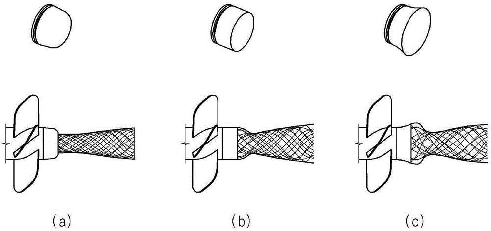
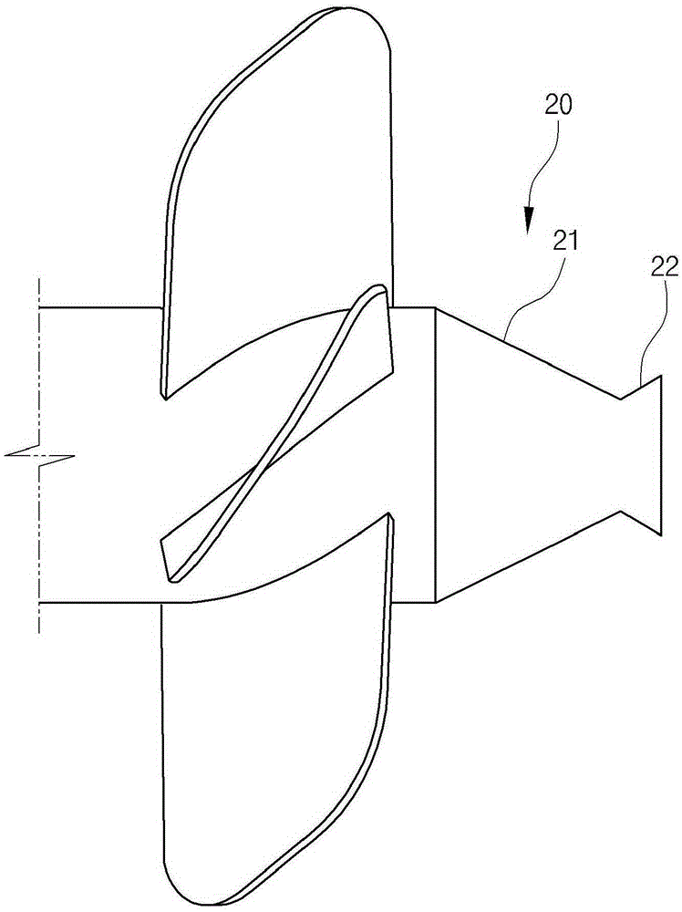
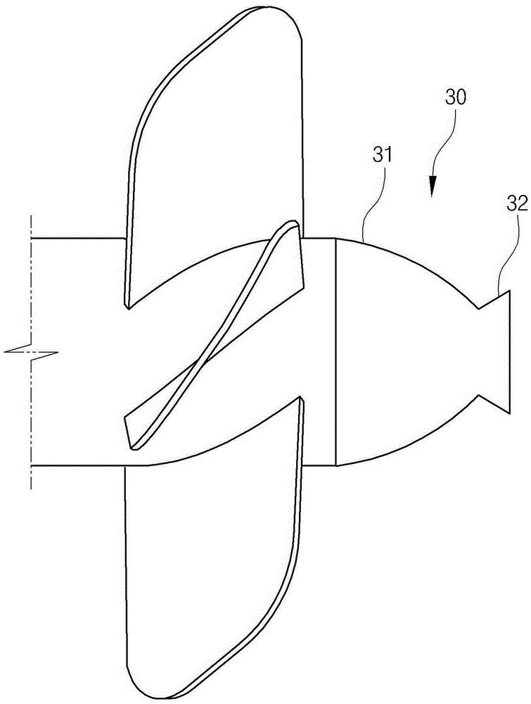
[0065] Specific embodiments of the composite propeller hub cap for reducing swirling flow and hub vortex and improving propulsion efficiency according to the present invention will be described in detail below with reference to the accompanying drawings.

[0066] It is stated in advance that the content described below is only an embodiment for implementing the present invention, and the present invention should not be limited to the content of the embodiment described below.

[0067] In order to simplify the description when describing the following embodiments of the present invention, the detailed description of the parts that are the same or similar to the prior art or can be easily understood and implemented by those skilled in the art will be omitted.

[0068] Meanwhile, in order to pursue simplification of description when describing the following embodiments of the present invention, the same or similar constituent elements are given the same symbol and detailed descrip...


PUM


Abstract

The present invention relates to a structure of a propeller cap. In order to solve the problem of a conventional propeller boss cap fin (PBCF) which requires precision processing and thus is difficult to manufacture and has high manufacturing costs, the present invention provides a combined propeller cap configured by combining a diffusion type propeller cap with the tip end of an existing contraction type propeller cap so that hub vortex cavitation occurring in the rear of a propeller can be reduced. In addition, provided is a combined propeller cap having a guide fin for reducing rotating flow and hub vortex and enhancing propulsion efficiency, the combined propeller cap being configured so as to be capable of additionally reducing occurrence of hub vortex cavitation due to attachment of a plate shaped guide fin to a contraction type portion of such a propeller cap or between a contraction type portion and a diffusion type portion thereof.

Description

technical field [0001] The present invention relates to a structure of a propeller cap (propellercap), in more detail, the present invention relates to a composite propeller cap for reducing swirling flow and propeller hub vortex and improving propulsion efficiency, which is used as a ship propulsion The hub vortex cavitation (hubvortexcavitation) that occurs behind the propeller used by the engine is reduced to reduce the noise and vibration of the ship and prevent the erosion and corrosion of the rudder (rudder). It can also improve propulsion efficiency and save fuel. [0002] Moreover, the present invention also relates to a composite propeller cap for reducing swirling flow and propeller hub vortex and improving propulsion efficiency. A small fin (fin) is formed to reduce the vortex of the propeller hub. Therefore, precision machining is required to design and manufacture the fin, which increases the difficulty of manufacture and leads to an increase in production cost. ...

Claims


Application Information

Patent Timeline
Patent Type & Authority Applications(China)
IPC IPC(8): B63H1/14B63H1/28
CPCB63H1/14B63H1/28B63H1/20
Inventor 薛汉信白府根金庆烈
Owner KOREA INST OF OCEAN SCI & TECH
Why Eureka
Try Eureka