Fuel injection valve for internal combustion engine

A technology of fuel injection pumps and internal combustion engines, which is applied in the direction of fuel injection pumps, fuel injection devices, charging systems, etc., to achieve the effect of compact structure and small size

Inactive Publication Date: 2016-03-02
ROBERT BOSCH GMBH
View PDF6 Cites 0 Cited by
  • Summary
  • Abstract
  • Description
  • Claims
  • Application Information

AI Technical Summary

Problems solved by technology

[0003] The problem on which the invention is based is solved by a fuel injection pump according to claim 1 and by a fuel container, a fuel system and a method according to the parallel claims

Method used


Image

  • Fuel injection valve for internal combustion engine
  • Fuel injection valve for internal combustion engine
  • Fuel injection valve for internal combustion engine

Examples


Embodiment Construction

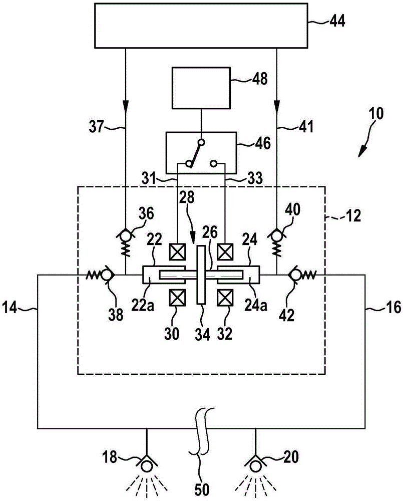
[0018] figure 1 A fuel system 10 for a two-cylinder internal combustion engine of a scooter (not shown), for example with a displacement of 50 ccm to 125 ccm, is shown schematically. The dotted box in the middle of the figure includes the fuel injection pump 12 embodied as a "dual stroke pump". The fuel injection pump 12 is now embodied symmetrically with respect to a vertical axis not shown in the drawing and is attached by means of fuel lines 14 and 16 to a first, pressure-controlled and outwardly opening injection valve 18 and a second injection valve, respectively. injection valve and 20 on. Second injection valve 20 is only required in the case of a two-cylinder internal combustion engine and is therefore optional.

[0019] The fuel injection pump 12 has a cylinder assembly with two cylinders 22 and 24 and a piston 26 movable axially therein (dual piston). The direction of movement of the piston 26 is figure 1 Medium is horizontal. A first axial end section of the pi...


PUM


Abstract

The invention relates to a fuel injection pump (12) for an internal combustion engine, comprising a cylinder arrangement (22, 24) having an axially displaceable piston (26) and a connection for a pressure-controlled injection valve (18, 20). According to the invention, the fuel injection valve (12) comprises an electromagnetic actuation device (28), said actuation device enabling the piston (26) to be moved in a first axial direct an in a second axial direction which is counter to the first.

Description

technical field [0001] The invention relates to a fuel injection pump according to the preamble of claim 1 as well as a fuel container, a fuel system and a method according to the side claims. Background technique [0002] Fuel systems for internal combustion engines are known on the market, in which fuel is pumped out of a fuel container by means of a fuel pump and delivered, for example under pressure, into a high-pressure accumulator (rail). The high-pressure accumulators are connected to the injection valves of the internal combustion engine, which are individually actuatable and can inject fuel in the respectively desired quantity into the combustion chambers of the internal combustion engine. So-called pump-nozzle or pump-line-nozzle assemblies are also known, in which a fuel pump delivers fuel directly to a pressure-controlled injection valve. Injection systems with distributor-injection pumps are also known. Contents of the invention [0003] The problem on which...

Claims


Application Information

Patent Timeline
Patent Type & Authority Applications(China)
IPC IPC(8): F02M57/02F02M59/10
CPCF02M59/10F02M57/027
Inventor F·特梅斯
Owner ROBERT BOSCH GMBH
Why Eureka
Try Eureka