Deep-cooling punching-shearing forming device for blank holder of micro-miniature workpiece and forming method thereof

A blank holder and micro-sized technology, which is applied to the cryogenic punching and shearing forming device and its forming field of micro-small workpieces, can solve the problems of poor cross-section appearance, low precision of forming cross-section, and uneven surface, so as to reduce the elongation rate , increase the boundary brittleness, improve the effect of machining accuracy

Inactive Publication Date: 2016-03-09
JILIN UNIV
View PDF8 Cites 4 Cited by
  • Summary
  • Abstract
  • Description
  • Claims
  • Application Information

AI Technical Summary

Problems solved by technology

At present, ordinary processing methods at room temperature are still used in the punching and shearing of micro-sized workpieces, such as high-speed punching or multiple times of punching and shearing assisted by ultrasound. For small parts, ordinary punching and shearing is used. There are many burrs on the section of the workpiece, the surface is uneven, and the appearance of the section is poor, especially the precision of the formed section is low

Method used


Image

  • Deep-cooling punching-shearing forming device for blank holder of micro-miniature workpiece and forming method thereof
  • Deep-cooling punching-shearing forming device for blank holder of micro-miniature workpiece and forming method thereof
  • Deep-cooling punching-shearing forming device for blank holder of micro-miniature workpiece and forming method thereof

Examples


Embodiment Construction

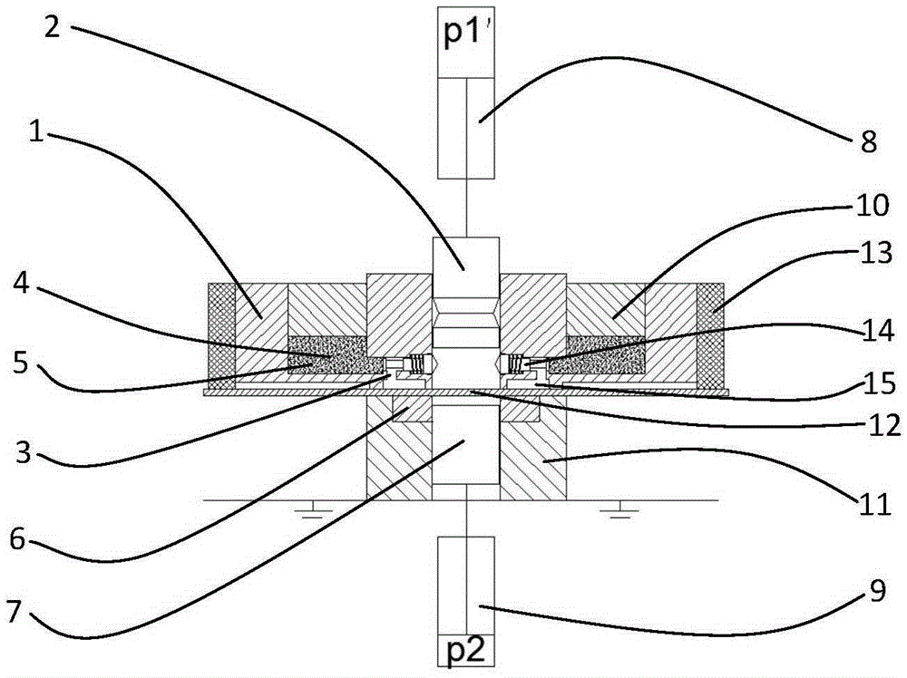
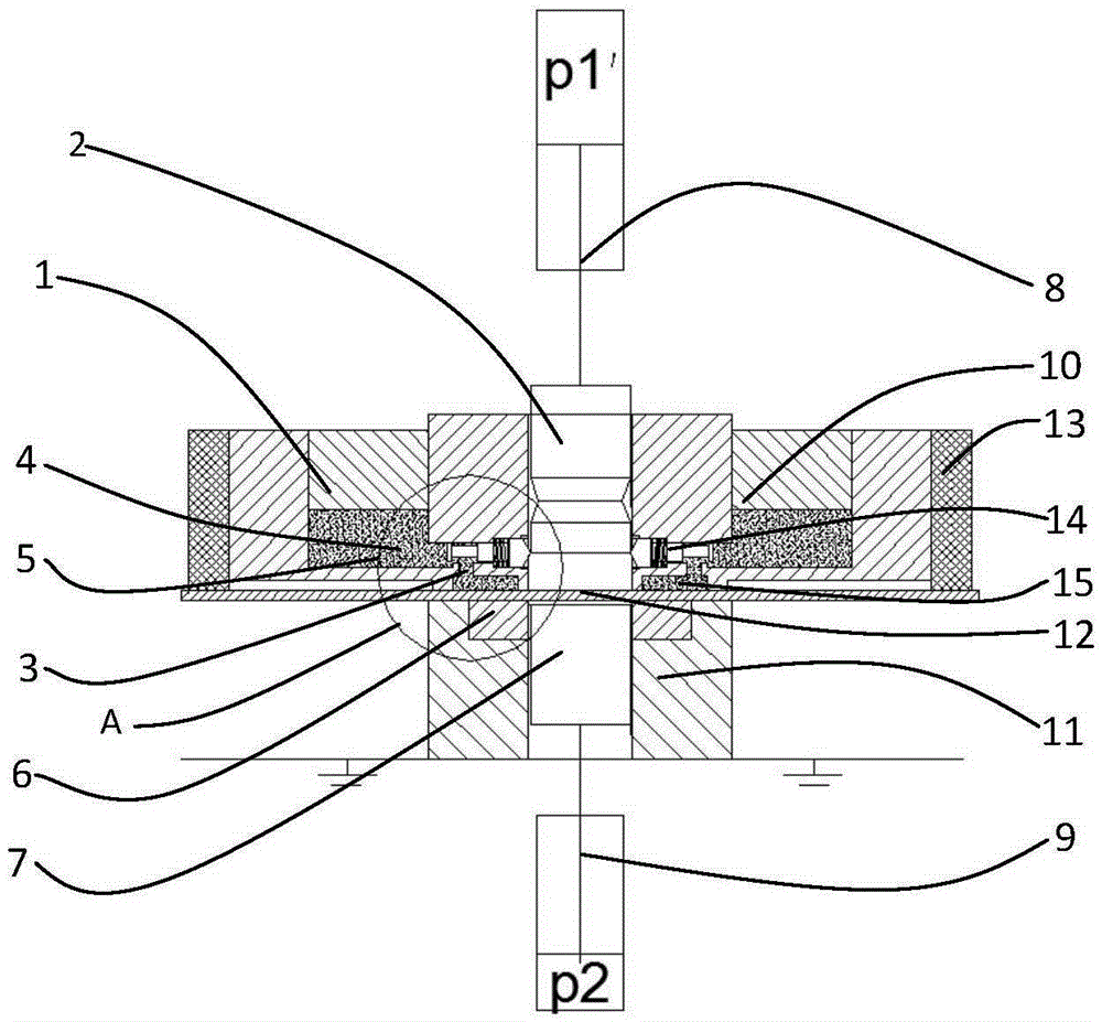
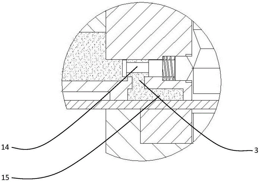
[0034] Such as figure 1 As shown in the figure, a cryogenic punching and shearing forming device for a micro-sized blank holder, the blank holder 1 has a storage tank 5 for storing a low-temperature solution 4, and at the bottom of the storage tank 5, there is a flow channel 3 leading to contact with the plate. There is a cut-off or open valve 14 in the flow channel 3, and the movement of the punch 2 driven by the hydraulic cylinder P1'8 in the blank holder 1 triggers the opening and closing of the valve 14; there is a floating piston 10 on the storage tank 5, and the blank holder The surrounding of the ring is coated with heat insulating material 13; the die 6 is placed in the die support 11 and fixed, and the ejector rod 7 driven by the hydraulic cylinder P29 moves in the die 6; the blank holder 5 can be Under the action, the plate 12 is compressed on the die 6 limits.

[0035] The blank holder 1 presses the plate 12 to form a closed cavity 15 .

[0036] The top surface of...


PUM

PropertyMeasurementUnit
Thicknessaaaaaaaaaa

Abstract

The invention relates to a deep-cooling punching-shearing forming device for a blank holder of a micro-miniature workpiece and a forming method thereof, and belongs to the field of mechanical engineering. The blank holder is provided with a storage groove for storing a low-temperature solution. A flow channel which leads to a plate and makes contact with the plate is formed in the bottom of the storage groove. A valve used for closing or opening is arranged in the flow channel. A male die driven by a hydraulic cylinder P1' moves in the blank holder to trigger the valve to be opened and closed. The storage groove is provided with a floating piston. The periphery of the blank holder is coated with a heat insulating material. A female die is arranged inside a female die support to be fixed. An ejection rod driven by a hydraulic cylinder P2 moves in the female die. The plate can be pressed on the edge of the female die by the blank holder under the action of force. The forming method based on the device comprises the five steps of plate clamping, cooling, punching and shearing, die releasing and shape detecting. The deep-cooling punching-shearing forming device for the blank holder of the micro-miniature workpiece and the forming method thereof have the advantages that the structure is novel, and when the micro-miniature workpiece is machined under the condition of deep cooling, it is beneficial to reducing rough edges and burrs, so that the machining precision of the workpiece is improved, and the mass production is achieved.

Description

technical field [0001] The invention belongs to the field of mechanical engineering and is used for a plastic forming method for punching and shearing micro-sized workpieces or through holes, in particular to a cryogenic punching and shearing forming device for micro-sized workpieces and a forming method thereof. Background technique [0002] Micro-small workpieces play a very important role in the electronics industry, and the contour and through-hole punching of micro-small workpieces play an important role in the field of micro-small workpiece processing. At present, ordinary processing methods at room temperature are still used in the punching and shearing of micro-sized workpieces, such as high-speed punching or multiple times of punching and shearing assisted by ultrasound. For small parts, ordinary punching and shearing is used. There are many burrs on the section of the workpiece, the surface is uneven, and the appearance of the section is poor, especially the precis...

Claims


Application Information

Patent Timeline
IPC IPC(8): B21D28/34B21D37/16B21D28/14
CPCB21D28/14B21D28/34B21D37/16
Inventor 胡志清刘昆赵继冀世军蔡中义刘纯国
Owner JILIN UNIV
Why Eureka
Try Eureka