Construction method for air bag type concrete project deformation joint water stop cavity mold

A technology of concrete and deformation joints, applied in marine engineering, earthwork drilling, water conservancy engineering and other directions, can solve the problems of prolonging the construction period, increasing labor, running out of soft asphalt, etc., and achieving the effect of convenient pouring, saving construction period, and convenient demoulding

Inactive Publication Date: 2016-03-02
王东华 +2
View PDF7 Cites 2 Cited by
  • Summary
  • Abstract
  • Description
  • Claims
  • Application Information

AI Technical Summary

Problems solved by technology

[0002] In existing concrete structures, such as retaining dams, reservoirs, subways, culverts, sluices, tunnels and other underground and underwater projects, due to the inability to pour continuously or the deformation of the foundation settlement (earthquake), or due to temperature changes Due to thermal expansion and contraction of concrete components caused by thermal expansion and contraction, deformation joints are often deliberately left during pouring. These gaps must take anti-leakage measures to prevent external water or groundwater from leaking into the structural space. A concrete groove is set between the stage concrete and the second stage concrete, and soft asphalt and copper sheets or rubber waterstops are arranged in the groove. However, this method requires prefabricated concrete grooves. The 3 sides of the groove are chiseled, which will prolong the construction period and increase labor. At the same time, because the length (height) of each concrete groove is generally only 50-100cm, the deformation gap must be formed by connecting multiple concrete grooves, so there will be multiple Horizontal gaps and irregular deformation of multiple concrete grooves will cause the leakage of soft asphalt in the subsequent pouring, and it is difficult to clean up; and the technology of using channel steel instead of concrete grooves in the patent application No. 2014100489253, although compared with the original construction This method can save costs and shorten the construction period, but because the channel steel must be kept in the dam body, it cannot be reused, and it still causes waste. Therefore, there is an urgent need for a cavity equipment that can prefabricate asphalt in the second-stage concrete section

Method used


Image

  • Construction method for air bag type concrete project deformation joint water stop cavity mold
  • Construction method for air bag type concrete project deformation joint water stop cavity mold
  • Construction method for air bag type concrete project deformation joint water stop cavity mold

Examples


Embodiment 1

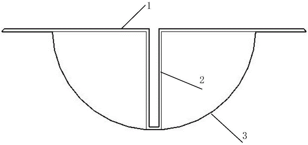
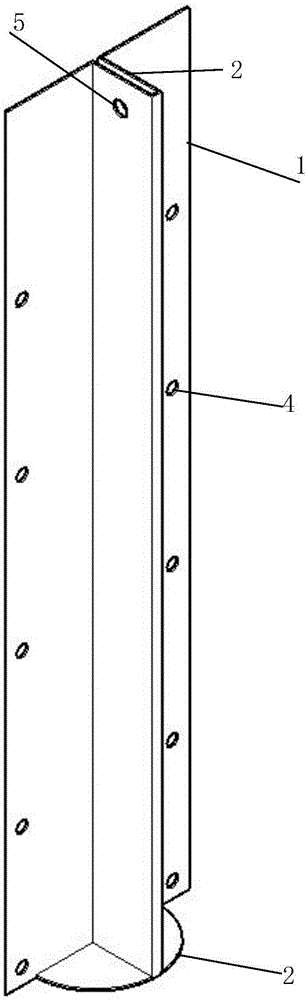
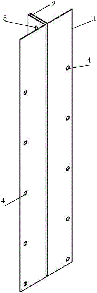
[0041] Embodiment 1, with reference to the accompanying drawings: a method for manufacturing a water-stop cavity mold for a deformation joint of an airbag type concrete project, the cavity mold comprising a skeleton 1 and an airbag, and is characterized in that it includes the following processes and steps:

[0042]1) Fabrication of skeleton 1: The skeleton 1 is a rectangular steel plate with a thickness of 2-4mm and a length greater than the height of the deformation seam by 20-40cm. The groove 2 is folded in the middle, or the groove 2 is welded, and the depth of the groove 2 is 15-30cm. The width of the groove 2 is 5-10cm, the width of the skeleton 1 contains the groove 2 30-50cm, the fixing holes 4 are arranged at a certain distance longitudinally on both sides of the skeleton 1, the hanging holes 8 are arranged on the upper groove 5 of the skeleton 1, and the skeleton The lower end of 1 is provided with a base 3, the radius of the base 3 is equal to the depth of the groove...


PUM


Abstract

The invention relates to a construction method for an air bag type concrete project deformation joint water stop cavity mold. The cavity mold comprises a skeleton and an air bag, a red copper water stop piece pre-embedded in the section of first-stage concrete is clamped in a groove by the cavity mold, air pressure is set in the air bag of the cavity mold, second-stage concrete is poured in layers, after initial setting of the concrete, air pressure in the air bag is released, the cavity mold is hung out, a semicircular cavity can be formed in the section of the second-stage concrete, and molten pitch is injected into the semicircular cavity to achieve the water stop function. The problem that deformation joint water leakage, caused by differential settlement or diastrophism of a stratum, of a water conservancy project can be solved, and the cavity mold can be used repeatedly.

Description

technical field [0001] The invention relates to a waterproof device for underground / underwater buildings, in particular to a construction method of a water-stop cavity mold for a bladder-type concrete engineering deformation joint. Background technique [0002] In existing concrete structures, such as retaining dams, reservoirs, subways, culverts, sluices, tunnels and other underground and underwater projects, due to the inability of continuous pouring or deformation due to foundation settlement (earthquake), or due to temperature changes For reasons such as thermal expansion and cold contraction of concrete components, deformation joints are often deliberately left during pouring. Anti-seepage measures should be taken for these gaps to prevent external water or groundwater from seeping into the structural space. A concrete groove is set between the first-stage concrete and the second-stage concrete, and soft asphalt and copper sheets or rubber water-stops are arranged in th...

Claims


Application Information

Patent Timeline
Patent Type & Authority Applications(China)
IPC IPC(8): E04G15/04
CPCE02B3/16E02D29/16E02D31/02E02D2250/0023E04G15/04E21D11/385
Inventor 张朝利
Owner 王东华
Why Eureka
Try Eureka