Foldable water stopping type cavity die for concrete deformation joint and manufacturing and construction method thereof

A technology of concrete and deformation joints, which is used in earth-moving drilling, water conservancy projects, artificial islands, etc., can solve the problems of irregular deformation of concrete grooves, non-reusable, soft asphalt running off, etc., to prevent cross-section interface dislocation, The section is neat and the construction period is saved

Inactive Publication Date: 2015-01-28
扬州市勘测设计研究院有限公司
View PDF5 Cites 2 Cited by
  • Summary
  • Abstract
  • Description
  • Claims
  • Application Information

AI Technical Summary

Problems solved by technology

[0002] In existing concrete structures, such as retaining dams, reservoirs, subways, culverts, sluices, tunnels and other underground and underwater projects, due to the inability to pour continuously or the deformation of the foundation settlement (earthquake), or due to temperature changes Due to thermal expansion and contraction of concrete components caused by thermal expansion and contraction, deformation joints and construction joints are often deliberately left during pouring. These gaps must take anti-leakage measures to prevent external water or groundwater from leaking into the structural space. The current common practice is A concrete groove is set between the first-stage concrete and the second-stage concrete, and soft asphalt and copper sheets or rubber waterstops are arranged in the groove. However, this method requires prefabricated concrete grooves. In order to make the concrete grooves and the second-stage concrete tightly combined, It is necessa

Method used


Image

  • Foldable water stopping type cavity die for concrete deformation joint and manufacturing and construction method thereof
  • Foldable water stopping type cavity die for concrete deformation joint and manufacturing and construction method thereof
  • Foldable water stopping type cavity die for concrete deformation joint and manufacturing and construction method thereof

Examples


Embodiment 1

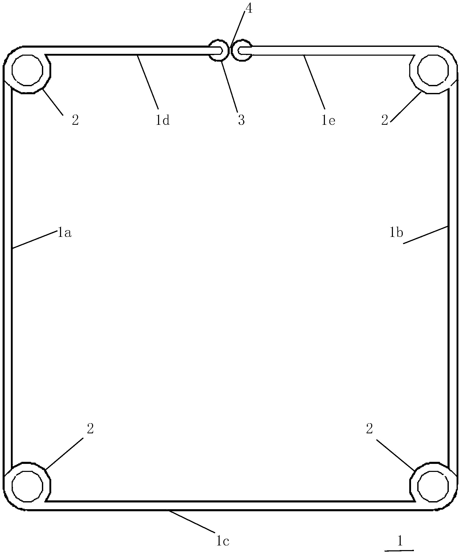
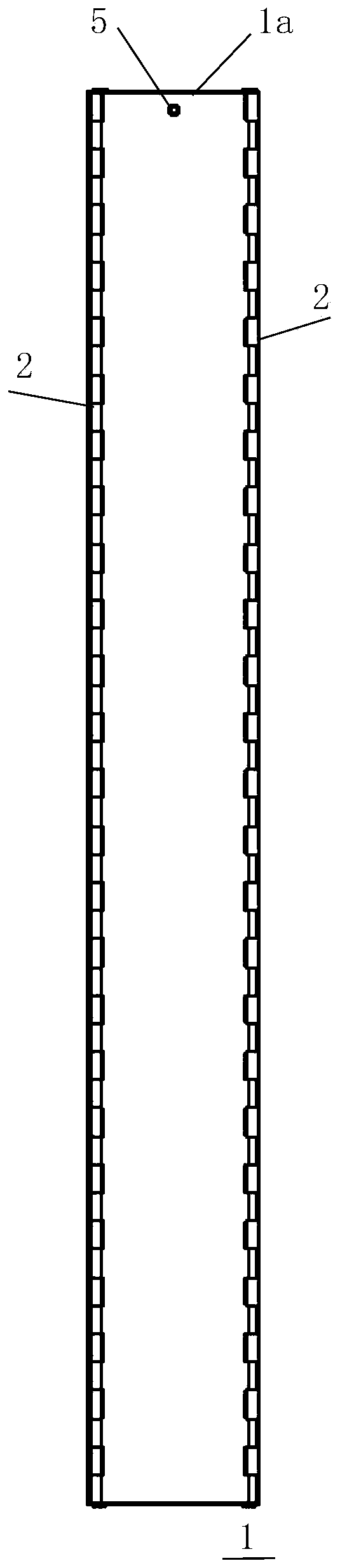
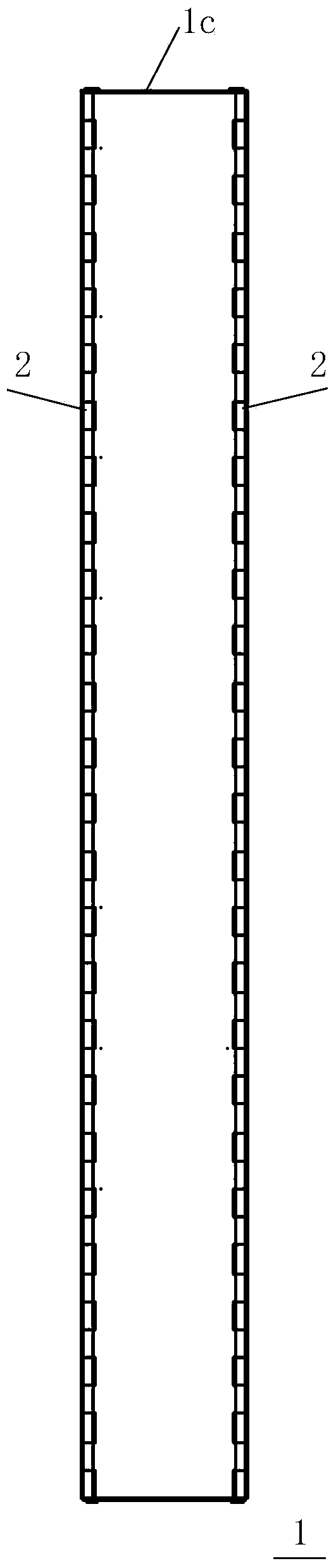
[0047] Embodiment 1, with reference to the accompanying drawings: a folding concrete deformation joint waterproof cavity mold, including a cavity mold body, the cavity mold 1 is composed of a rear side plate 1c, a left side plate 1a, a right side plate 1b and a left front Plate 1d and right front plate 1e are composed of movable links. The cavity mold 1 is rectangular in plan view and a middle seam 4 is provided between the front left and right front plates. When the cavity mold 1 is applied, the front of the cavity mold 1 is aligned with the pre-set The water-stop sheet 7 buried in the section of the first-stage concrete 6, the water-stop sheet 7 is inserted into the cavity mold through the middle seam 4, and the second-stage concrete 9 is poured. After the initial setting of the second-stage concrete 9, the The cavity mold 1 is hoisted out, and a cavity 10 for injecting molten asphalt 11 is formed at the section of the second-stage concrete 9 .

[0048] More preferably, the ...


PUM


Abstract

The invention relates to a foldable water stopping type cavity die for a concrete deformation joint and manufacturing and construction method thereof. The foldable water stopping type cavity die comprises a cavity die body. The foldable water stopping type cavity die is characterized in that the cavity die is formed by movably chaining a rear side plate, a left side plate, a right side plate, a left front plate and a right front plate; the cavity die is rectangular by overlooking, and a medium clearance is formed between the left front plate and the right front plate in the front part; when in use, the front part of the cavity die is aligned with a water stopping sheet which is embedded in the first phase concrete section, the water stopping sheet extends into the cavity die through the medium clearance, then the second phase concrete can be poured, the cavity die is hoisted out after the second phase concrete is initially set, and thus the cavity capable of pouring molten asphalt can be formed in the second phase concrete section.

Description

technical field [0001] The invention relates to an underground / underwater building waterproof device, in particular to a foldable concrete deformation joint waterproof cavity mold and its manufacturing and construction methods. Background technique [0002] In existing concrete structures, such as retaining dams, reservoirs, subways, culverts, sluices, tunnels and other underground and underwater projects, due to the inability to pour continuously or the deformation of the foundation settlement (earthquake), or due to temperature changes Due to thermal expansion and contraction of concrete components caused by thermal expansion and contraction, deformation joints and construction joints are often deliberately left during pouring. These gaps must take anti-leakage measures to prevent external water or groundwater from leaking into the structural space. The current common practice is A concrete groove is set between the first-stage concrete and the second-stage concrete, and s...

Claims


Application Information

Patent Timeline
IPC IPC(8): E02B3/16E02D29/16E02D31/02E21D11/38
CPCE02B3/16E02D29/16E02D31/02E21D11/38E21D11/385
Inventor 张朝利
Owner 扬州市勘测设计研究院有限公司
Why Eureka
Try Eureka