
Automatic fixing device for screw machine

A fixing device and screw machine technology, applied in metal processing, metal processing equipment, manufacturing tools, etc., can solve the problems of unfavorable scale, automatic production, low work efficiency, low production efficiency, etc., and achieve good market promotion and use value, The effect of realizing automatic control and saving labor costs

Inactive Publication Date: 2016-03-09
ZHUHAI SEPSTAR ELECTRONICS
View PDF8 Cites 8 Cited by
  • Summary
  • Abstract
  • Description
  • Claims
  • Application Information

AI Technical Summary

Problems solved by technology

[0002] At present, when products on the market are assembled from various parts into products, screws are usually used to lock and reinforce each part. Traditional screw locking or loosening and unloading operations generally use manual operations. The operator uses a screwdriver to screw each screw Lock each component to assemble it into the product to be produced. When loosening the screws, the operator uses a screwdriver to remove the screws one by one. This original manual operation method requires more assemblers. Screwing and aligning screw heads still takes a lot of work time and energy, so its efficiency is low, output is low, operation is inconsistent, product quality cannot be guaranteed, manual assembly is not standardized, work efficiency is low, and labor intensity is high , It is not conducive to the implementation of large-scale and automatic production. It is time-consuming and laborious to complete manually, the production efficiency is relatively low, and there will be problems such as uneven tightening force.
[0003] In response to the above problems, some screw machines have appeared on the market to replace manual locking or loosening of screws. However, these traditional screw machines usually have only one pneumatic screwdriver for each screw machine to lock or loosen the screws. The function of loosening and unloading cannot realize the locking or loosening of batch screws at the same time, the production speed is slow, and the efficiency is still relatively low. Therefore, it is necessary to design an automatic fixing device with multiple stations and capable of continuous work.

Method used


Image

  • Automatic fixing device for screw machine
  • Automatic fixing device for screw machine

Examples


Embodiment Construction

[0022] The following will clearly and completely describe the technical solutions in the embodiments of the present invention with reference to the accompanying drawings in the embodiments of the present invention. Obviously, the described embodiments are only some, not all, embodiments of the present invention. Based on the embodiments of the present invention, all other embodiments obtained by persons of ordinary skill in the art without creative efforts fall within the protection scope of the present invention.

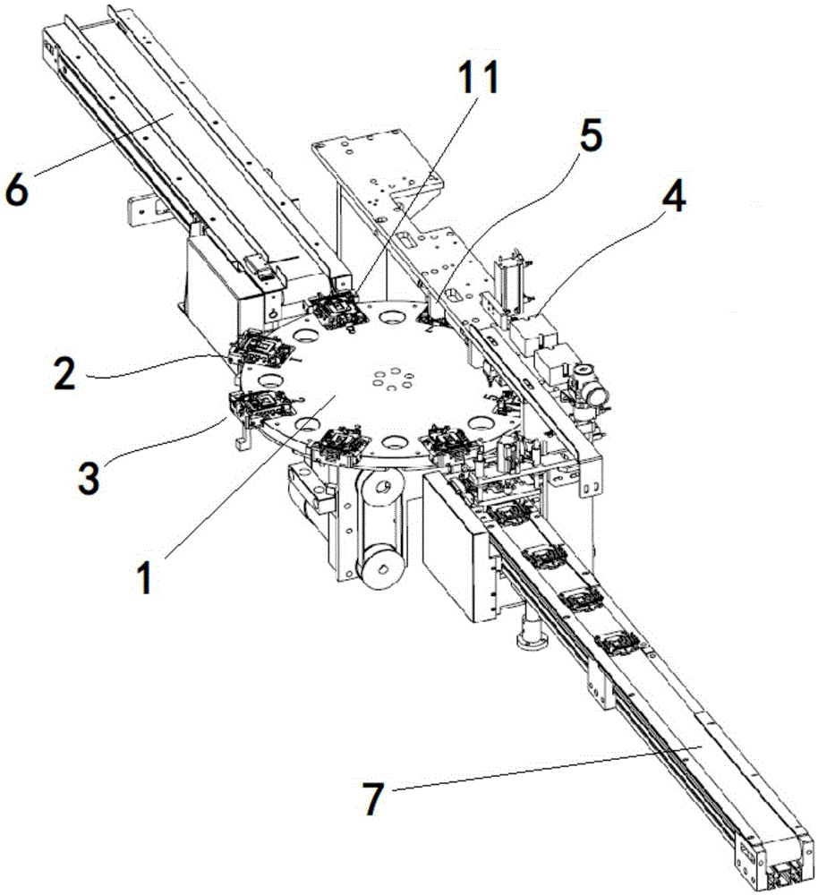
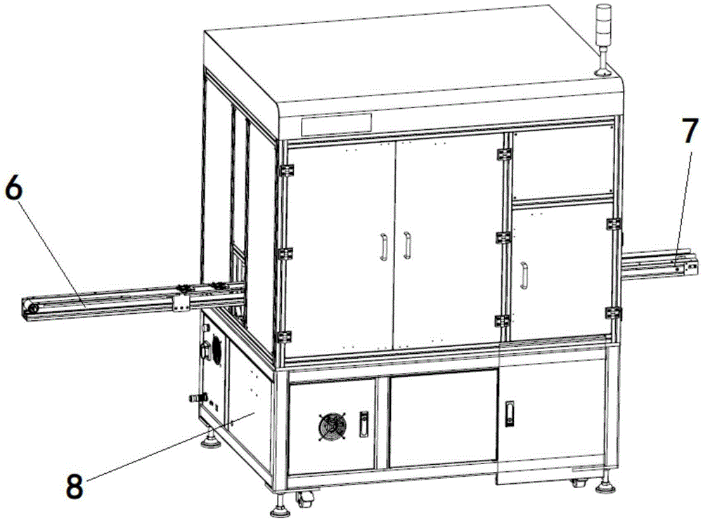
[0023] In one embodiment, such as figure 1 and figure 2 As shown, this embodiment provides an automatic fixing device for a screw machine, including a rotatable bottom bracket 1, the bottom bracket 1 is a disc structure, and the bottom bracket 1 is along the outer edge There are 8 bottom plate accommodation grids 11 evenly distributed in the circumferential direction, and fixing fixtures are arranged in the bottom plate accommodation grids 11, and the fixing fixt...


PUM


Abstract

The invention relates to the field of mechanical automation equipment and discloses an automatic fixing device for a screw machine. The automatic fixing device comprises a rotatable bottom plate bracket, wherein a plurality of bottom plate containing grids are uniformly distributed on the bottom plate bracket along the peripheral direction. The automatic fixing device further comprises a feeding mechanism and a material taking mechanism, wherein both the feeding mechanism and the material taking mechanism are arranged on the periphery of the bottom plate bracket; the bottom plate bracket is rotated, so that two of the bottom plate containing grids are respectively opposite to the feeding mechanism and the material taking mechanism; in the rotation process, the bottom plate bracket passes through a nut containing mechanism, a spring containing mechanism, a bolt pushing mechanism and a self-tapping screw pushing mechanism. According to the automatic fixing device, the rotatable bottom plate bracket containing a plurality of bottom plate containing grids is adopted, the bottom plate bracket rotates for a specified angle and stops under the control of a controller, and therefore a process is completed. The device has the advantages of being simple in structure and reasonable in design and can realize continuous automatic operation, the working efficiency is improved, and the homogeneity of product is high.

Description

technical field [0001] The invention relates to the field of mechanical automation equipment, in particular to an automatic fixing device for a screw machine. Background technique [0002] At present, when products on the market are assembled from various parts into products, screws are usually used to lock and reinforce each part. Traditional screw locking or loosening and unloading operations generally use manual operations. The operator uses a screwdriver to screw each screw Lock each component to assemble it into the product to be produced. When loosening the screws, the operator uses a screwdriver to remove the screws one by one. This original manual operation method requires more assemblers. Screwing and aligning screw heads still takes a lot of work time and energy, so its efficiency is low, output is low, operation is inconsistent, product quality cannot be guaranteed, manual assembly is not standardized, work efficiency is low, and labor intensity is high , It is n...

Claims


Application Information

Patent Timeline
Patent Type & Authority Applications(China)
IPC IPC(8): B23P19/06
CPCB23P19/06B23P19/001B23P19/007
Inventor 姚志杰谭辉洪俊
Owner ZHUHAI SEPSTAR ELECTRONICS
Learn More