Machining locating method of glass guide rail

A glass guide rail and positioning method technology, applied in positioning devices, metal processing equipment, metal processing mechanical parts, etc., can solve problems such as poor stability of the clamping mechanism, and achieve the effect of avoiding large vibrations

Inactive Publication Date: 2016-03-09
SICHUAN JINFENG CONSTR
View PDF0 Cites 0 Cited by
  • Summary
  • Abstract
  • Description
  • Claims
  • Application Information

AI Technical Summary

Problems solved by technology

[0004] The invention provides a processing and positioning method for glass guide rails, which solves the problem of poor stability of the clamping mechanism when cutting glass guide rails, so as to achieve the purpose of stable and efficient processing

Method used


Image

  • Machining locating method of glass guide rail

Examples


Embodiment 1

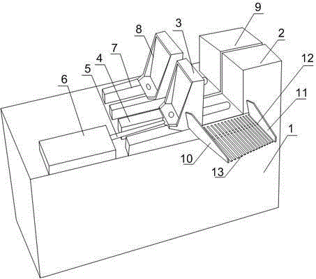
[0021] Such as figure 1 As shown, the present invention is first on the frame of the processing positioning device, the movable baffle and the fixed baffle form a clamping unit that can change the clamping gap according to the shape and size of the glass guide rail, and the fixed baffle that is set can adjust the glass guide rail. Playing a position-limiting role, the movable baffle can quickly advance and retreat under the push of the hydraulic mechanism to clamp or loosen the glass guide rail; during the material cutting process, the glass guide rail is close to the inner wall of the fixed baffle, and the movable baffle Driven by the hydraulic mechanism, it approaches the fixed baffle until the glass guide rail is clamped, and finally the glass guide rail is cut by the cutting mechanism; the processed glass guide rail slides directly and quickly to the special glass guide rail collection equipment through the discharge port ; wherein the processing and positioning device inc...

Embodiment 2

[0023] Such as figure 1 As shown, on the basis of Embodiment 1, the present embodiment includes a left baffle plate 10, a right baffle plate 11, and an inclined base plate 12. Connected, the base plate 12 includes a plurality of sliding rods 13 arranged side by side; the discharge port formed by the left baffle plate 10, the right baffle plate 11 and the bottom plate 12 provides a guiding function for the processed materials and can guide the materials to special collection equipment In the middle, it is beneficial to centralized collection; the inclined bottom plate 12 can make the material slide down automatically under the action of its own gravity. Chips leak out, avoiding the waste chips sliding to the collection equipment with the material and affecting the collection efficiency.

Embodiment 3

[0025] Such as figure 1 As shown, the present embodiment is based on Embodiment 1, the hydraulic mechanism includes a hydraulic cylinder 6 and a hydraulic motor, the hydraulic cylinder 6 is arranged on the same level as the movable baffle 3, the guide rail 4 is a U-shaped groove, and the hydraulic cylinder One end of the output end 5 passing through the U-shaped groove is connected to the bottom end of the movable baffle 3 , and the other end of the U-shaped groove is connected to the fixed baffle 2 . In view of defects such as unstable clamping of mechanical clamping and easy noise generation of pneumatic clamping, on the same horizontal plane, the hydraulic motor converts hydraulic energy into mechanical energy output, and the output end 5 of the hydraulic cylinder drives the movable baffle 3 to maintain a stable and fast speed. Back-and-forth linear motion works; the movable baffle 3 is slidably arranged on the U-shaped groove, and the opening of the U-shaped groove can be ...


PUM


Abstract

The invention discloses a machining locating method of a glass guide rail. The machining locating method comprises the steps that a clamping unit capable of changing a clamping clearance according to the appearance and size of the glass guide rail is firstly composed of a movable baffle and a fixed baffle on a rack of a machining locating device, the arranged fixed baffle can achieve the function of limiting the glass guide rail, and the movable baffle can be pushed by a hydraulic mechanism to quickly advance and retreat so as to clamp or loosen the glass guide rail; when the material cutting procedure is carried out, the glass guide rail is closely attached to the inner wall of the fixed baffle, the movable baffle is pushed by the hydraulic mechanism to move close to the fixed baffle till the glass guide rail is clamped, and finally the glass guide rail is cut by a cutting mechanism; and the machined glass guide rail directly and quickly slides towards dedicated glass guide rail collecting equipment through a discharging opening.

Description

technical field [0001] The invention relates to a processing and positioning device, in particular to a processing and positioning method for a glass guide rail. Background technique [0002] The glass guide rail and the window frame of the car together form a glass guide and protection mechanism. The glass guide rail is usually stamped or rolled with a steel plate, and then welded or fixed on the door with bolts to guide the smooth lifting of the window glass. And the important role of the limit; the cross section of the glass guide rail is generally a U-shaped groove, and the two ends of the U-shaped groove are designed as a bending structure, the purpose is to clamp the glass guide groove and prevent it from falling off. The strength of the glass guide rail directly affects the lifting of the window. The material of the guide rail body is generally cold-rolled steel plate SPCC, and the thickness of the guide rail is 0.7mm or 0.8mm. The material of the guide rail bracket i...

Claims


Application Information

Patent Timeline
Patent Type & Authority Applications(China)
IPC IPC(8): B23Q3/08
CPCB23Q3/082
Inventor 何学友
Owner SICHUAN JINFENG CONSTR
Why Eureka
Try Eureka