Yarn winding device

A winding device and yarn technology, which is applied in the directions of transportation and packaging, delivery of filamentous materials, thin material processing, etc., can solve the problems of longer yarn and longer time spent on jointing, etc., to achieve length suppression and shortening the effect of time

Active Publication Date: 2016-03-09
MURATA MASCH LTD
View PDF9 Cites 5 Cited by
  • Summary
  • Abstract
  • Description
  • Claims
  • Application Information

AI Technical Summary

Problems solved by technology

In this case, the discarded yarn becomes longer and the time taken for piecing becomes longer

Method used


Image

  • Yarn winding device
  • Yarn winding device
  • Yarn winding device

Examples


Embodiment Construction

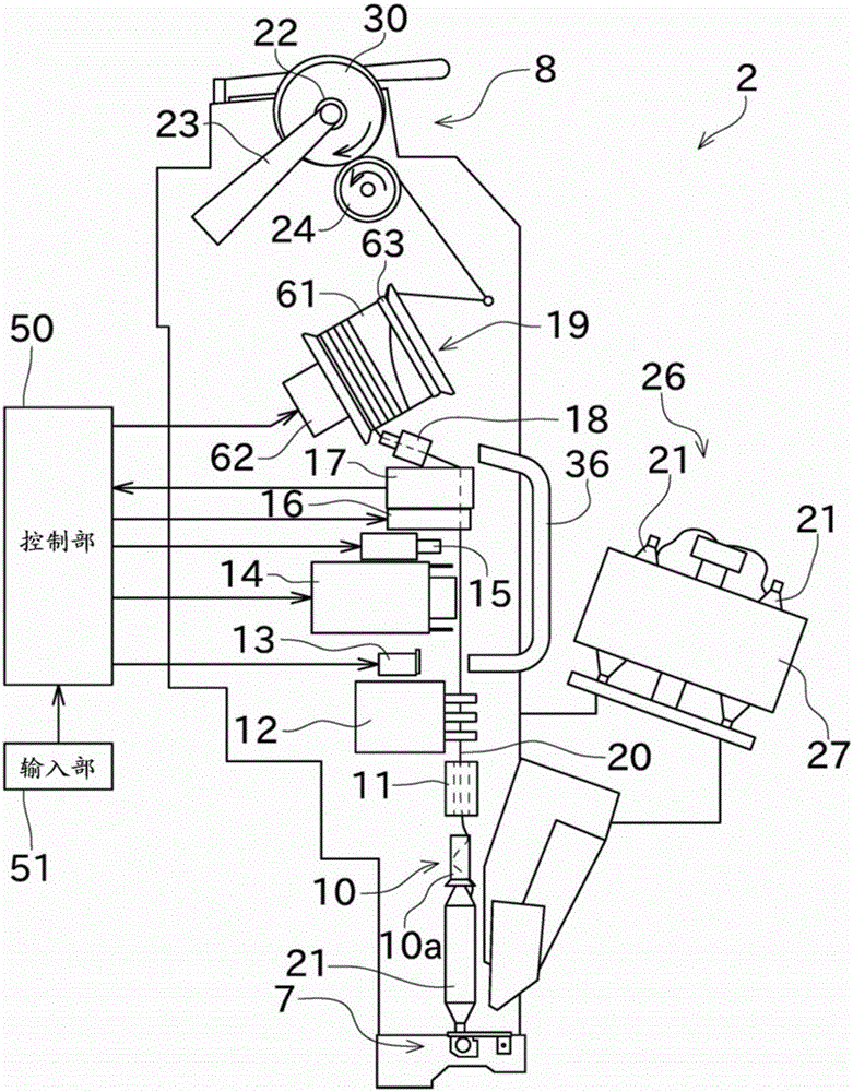
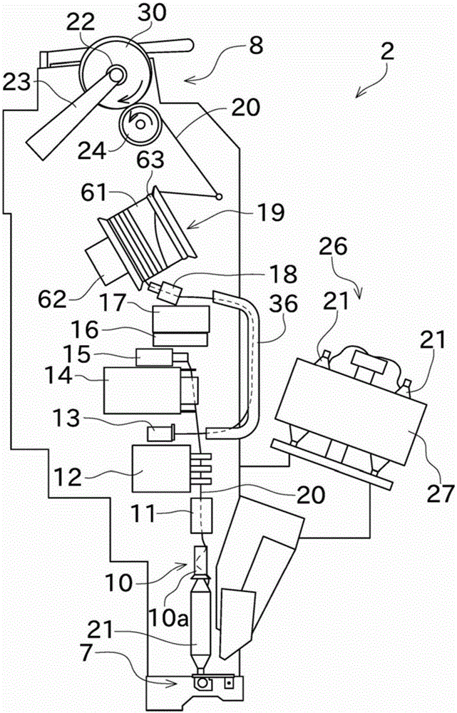
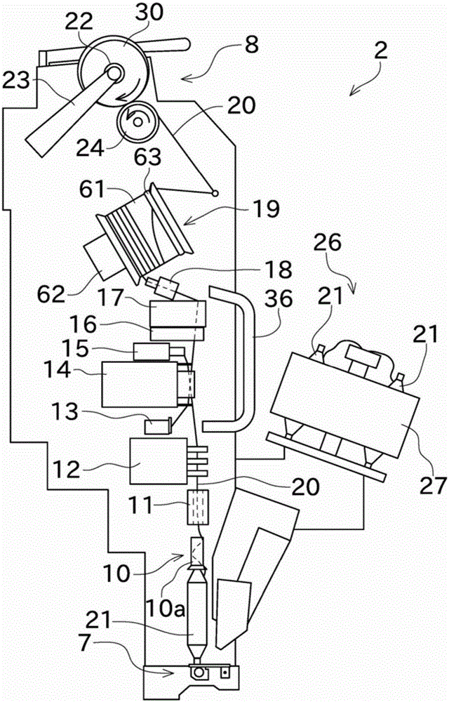
[0034] Next, embodiments of the present invention will be described. First, refer to figure 1 The outline of the automatic winder (yarn winding device) will be described. The automatic winder has a structure in which a plurality of winder units 2 are arranged in parallel. In addition, this automatic winder includes a body management device (not shown in the figure) for collectively managing the winder unit 2, and a blower box (not shown in the figure) provided with a compressed air source and a negative pressure source.

[0035] like figure 1As shown, the winding unit 2 mainly includes a control unit 50 , a yarn supplying bobbin support unit (yarn supplying unit) 7 , and a winding unit (package forming unit) 8 . The winding unit 2 is configured to unwind the yarn (spun yarn) 20 supported by the yarn supplying bobbin 21 supported by the yarn supplying bobbin support portion 7 and wind it back into the package 30 . In addition, in the following description, the upstream side...


PUM


Abstract

An automatic winder (yarn winding- device) includes a yarn storage device (19), a yarn joining device (14), an upper yarn pull-out section (18), and a control section. The yarn storage device (19) winds and temporarily stores a yarn (20) when a storage roller (61) is rotated. When guiding the yarn (20) from the yarn storage device (19) to the yarn joining device (14), the control section calculates an instructed number of reverse rotations, which is the number of times to rotate the storage roller (61) in a direction opposite to a direction of winding, and controls the storage roller (61) such that the number of reverse rotations of the storage roller (61) becomes the instructed number of reverse rotations.

Description

technical field [0001] The present invention relates to a yarn winding device including a yarn storage device and a yarn joining device. Specifically, it relates to control performed when pulling out the yarn from the yarn storage device at the time of piecing. Background technique [0002] Conventionally, there is known a yarn winding device that temporarily stores the yarn unwound from the yarn supplying bobbin in the yarn storage device, and winds the yarn from the yarn storage device to form a package. When the yarn winding device unwinds all the yarn in the yarn supplying bobbin, a new yarn supplying bobbin is supplied. The yarn winding device winds the new yarn feeding bobbin after using the jointing device to splice the yarn of the new yarn feeding bobbin and the yarn of the yarn storage device. Such a yarn winding device is disclosed in JP 2010-47407 A and WO 2011 / 040545 A. [0003] Here, in order to perform the yarn joining by the yarn joining device, the yarn on...

Claims


Application Information

Patent Timeline
Patent Type & Authority Applications(China)
IPC IPC(8): B65H54/42
CPCB65H51/22B65H67/081B65H2701/31
Inventor 阵山达夫
Owner MURATA MASCH LTD
Why Eureka
Try Eureka