Movable drilling guiding and positioning device and drilling guiding and positioning method

A guiding positioning and mobile technology, which is applied in the direction of earth mover/excavator, construction, etc., can solve the problems that the steel cage cannot be translated in place, the scheme of one slot and two cages cannot be implemented, and the pipeline cannot be slotted, etc., to achieve the solution Problems in connecting wall construction, avoiding incomplete drilling, and avoiding the effect of relocation

Active Publication Date: 2016-03-09
POWERCHINA RAILWAY CONSTR
View PDF4 Cites 4 Cited by
  • Summary
  • Abstract
  • Description
  • Claims
  • Application Information

AI Technical Summary

Problems solved by technology

[0004] However, when the pipeline is wide, the scheme of one trough and two cages cannot be implemented. For example, in the Huaqiang North Area of ​​Shenzhen Metro and the ground connection wall project of Huangmugang Station, some communication pipelines are as wide as 120cm, buried about 100cm deep, and some high-voltage power pipelines are as wide as 100cm. 75cm, about 70cm buried depth
For this type of pipeline, when the ordinary scheme of one trough and two cages is adopted, troughs cannot be formed under the pipeline, and because the pipeline is relatively wide, the reinforcement cage needs to be moved at least fifty or sixty centimeters. Bringing resistance and causing the lower part of the steel cage to fail to move in place

Method used


Image

  • Movable drilling guiding and positioning device and drilling guiding and positioning method
  • Movable drilling guiding and positioning device and drilling guiding and positioning method
  • Movable drilling guiding and positioning device and drilling guiding and positioning method

Examples


Embodiment Construction

[0031] The present invention is further described below in conjunction with accompanying drawing and embodiment:

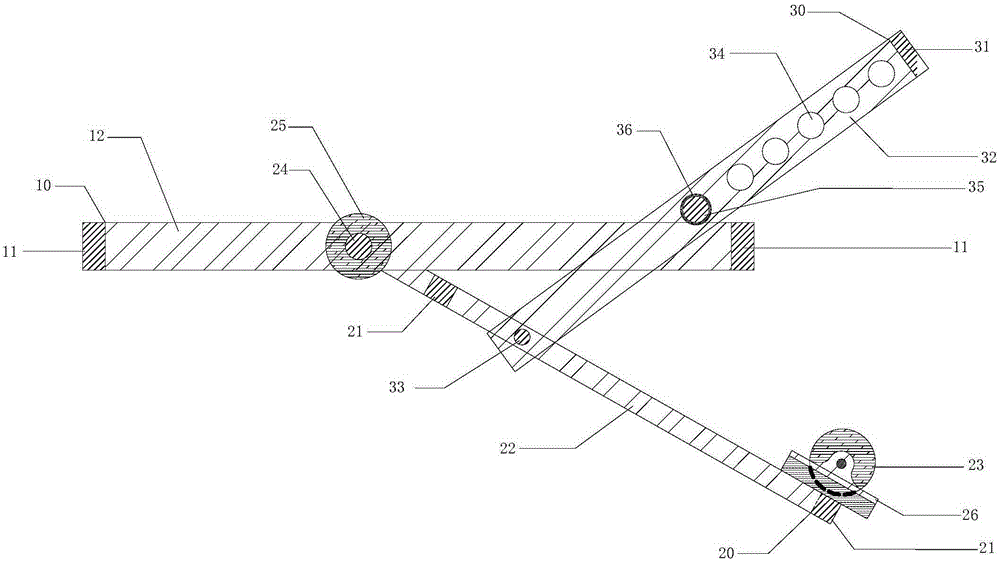
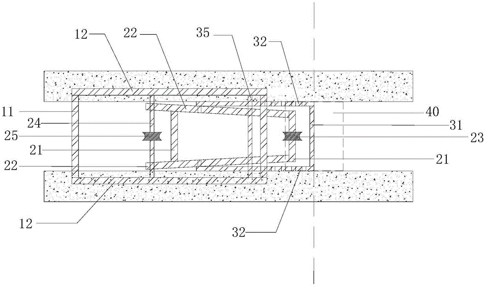
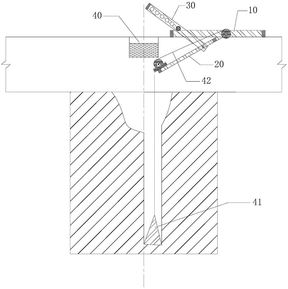
[0032] like figure 1 As shown, a mobile drilling guide positioning device includes a base bracket 10, a first positioning bracket 20 and a second positioning bracket 30,

[0033] The base support 10 adopts a frame structure, and the two base flat sides 11 are respectively connected to the two ends of the two base side vertical sides 12, and the two base side vertical sides 12 are provided with a number of symmetrical base positioning holes. Among them, the bottom ends of the two base side vertical edges 12 are respectively provided with protective rods, and the two protective rods are respectively fixed on the fixing pieces provided on the bottom ends of the two base lateral vertical edges by bolts;

[0034] The first positioning bracket 20 adopts a frame structure, and a first positioning flat side 21 is connected to one end of two first positioning side vertica...


PUM


Abstract

The invention discloses a movable drilling guiding and positioning device. The movable drilling guiding and positioning device is characterized by comprising a base support, a first positioning support and a second positioning support; the base support is of a frame structure; a plurality of base positioning holes are symmetrically formed in two vertical side edges of a base; the first positioning support is of a frame structure; a positioning pulley is installed on a first horizontal positioning edge of the first positioning support, and a pulley rod of a base pulley is connected to the other first horizontal positioning edge of the first positioning support; after the pulley rod penetrates through the two first vertical positioning side edges, the two ends of the pulley rod are fixed to the two vertical side edges of the base through adjustable fixing sets; the second positioning support is of a U-shaped structure; the two ends of a U-shaped opening are fixed to the two first vertical positioning side edges through movable shafts; a plurality of symmetrical second positioning support positioning holes are formed in the two second vertical positioning side edges; a positioning rod penetrates through the two symmetrical second positioning support positioning holes and then penetrates through two symmetrical fixed through pipes. By means of the movable drilling guiding and positioning device and the drilling guiding and positioning method, even wall construction under pipelines is achieved, pipeline modification in city building envelope construction is avoided, and the even wall construction under ultra-wide pipelines is achieved.

Description

technical field [0001] The invention relates to the construction field of foundation pit enclosure structures, in particular to a mobile drilling guiding and positioning device and a drilling guiding and positioning method. Background technique [0002] At present, when pipelines are encountered in the construction of ground connection walls in prosperous urban areas, the method of relocation is usually adopted. This method is difficult to operate and the cost is high. In special cases, pipelines cannot be relocated. [0003] When the pipeline is narrow (generally within 20cm), it basically does not affect the groove formation, and the construction of one groove and two cages can be adopted. [0004] However, when the pipeline is wide, the scheme of one trough and two cages cannot be implemented. For example, in the Huaqiang North Area of ​​Shenzhen Metro and the ground connection wall project of Huangmugang Station, some communication pipelines are as wide as 120cm, buried ...

Claims


Application Information

Patent Timeline
Patent Type & Authority Applications(China)
IPC IPC(8): E02F5/02E02F5/14
CPCE02F5/02E02F5/14
Inventor 刘永波段景川任立志胡德华谭瑞周方锡雄
Owner POWERCHINA RAILWAY CONSTR
Why Eureka
Try Eureka