Fireproof and heat-insulation metal wall

A wall and metal technology, which is applied in the field of fire-proof and heat-insulating metal walls, can solve the problems of environmental pollution, weak structure, and easy collapse, etc., and achieve the effects of improving safety, firm and reliable structure, and increasing strength

Inactive Publication Date: 2016-03-09
CHONGQING TUOZHUO METAL MATERIALS CO LTD
View PDF0 Cites 0 Cited by
  • Summary
  • Abstract
  • Description
  • Claims
  • Application Information

AI Technical Summary

Problems solved by technology

[0002] The walls used in power stations and other occasions are usually common concrete structures with low strength. In the event of earthquakes, fires, etc., they are prone to collapse and the structure is not firm. At the same time, due to the radiation during the operation of some equipment, the surrounding environment polluted

Method used


Image

  • Fireproof and heat-insulation metal wall

Examples


Embodiment 1

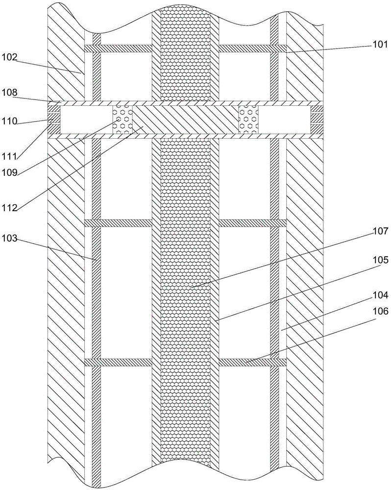
[0019] Such as figure 1 As shown, a fire-proof and heat-insulating metal wall includes an inner wall 101 and an outer wall 102 made of metal materials, and the inner wall 101 and the outer wall 102 are arranged between There is a cavity, and heat insulation layers 103 are respectively arranged on the facing surfaces of the inner wall 101 and the outer wall 102, and the inner wall 101 and the outer wall 102 are opposite to each other. Grooves 104 are respectively arranged on the surface, and the grooves 104 are arranged along the height direction of the inner wall 101, between the inner wall 101 and the outer wall 102 The middle part of the cavity is provided with a reinforcing rib 105 arranged vertically, and reinforcing ribs 106 are respectively arranged on both sides of the reinforcing rib 105, and the reinforcing ribs 106 are arranged at equal intervals along the height direction of the reinforcing rib 105. One end of the reinforcing rib 106 is fixedly connected to the sid...

Embodiment 2

[0022] In this embodiment, on the basis of Embodiment 1, in order to improve the sound insulation effect of the overall structure, in this embodiment, preferably, the inside of the reinforcing rib 105 is a hollow structure, and the middle part of the reinforcing rib 105 is provided with a sound-insulating sponge 107 . In this embodiment, by arranging the sound-proof sponge in the cavity in the middle of the reinforcing rib, the sound-proof effect can be achieved and the possibility of burning the sound-proof sponge can be reduced.

[0023] Further preferably, in order to facilitate installation, in this embodiment, the sound-insulating sponge 107 is bonded to the inner side wall of the reinforcing rib 105 by a fireproof adhesive. Since the sound-insulating sponge has certain flammability, in this embodiment, a fireproof adhesive is used to prevent the sound-insulating sponge from burning.

[0024] In order to make the overall structure have a certain ventilation effect, in th...


PUM


Abstract

The invention discloses a fireproof and heat-insulation metal wall which comprises an inner-layer wall body and an outer-layer wall body made of a metal material, wherein a cavity is formed between the inner-layer wall body and the outer-layer wall body; heat-insulation layers are respectively arranged on the opposite surfaces of the inner-layer wall body and the outer-layer wall body; grooves are respectively formed in opposite surfaces of the inner-layer wall body and the outer-layer wall body; reinforcing ribs which are perpendicularly arranged are arranged on the middle part of the cavity between the inner-layer wall body and the outer-layer wall body; strengthening ribs are respectively arranged at the two sides of each reinforcing rib; one end of each reinforcing rib is fixedly connected to the side wall of the corresponding strengthening rib; and the other end of the reinforcing rib respectively penetrates through the heat-insulation layer at the same side, and is blocked into the groove at the same side. The fireproof and heat-insulation metal wall adopts inner and outer layers of metal wall body structures, and can have good radiation insulation performance while the strength of the wall body is guaranteed; and meanwhile, the heat-insulation layers are adopted, so that better heat insulation effect is achieved under conditions such as a fire hazard and the like.

Description

technical field [0001] The invention relates to a fire-proof and heat-insulating metal wall body. Background technique [0002] The walls used in power stations and other occasions are usually common concrete structures with low strength. In the event of earthquakes, fires, etc., they are prone to collapse and the structure is not firm. At the same time, due to the radiation during the operation of some equipment, the surrounding environment polluted. Contents of the invention [0003] The purpose of the present invention is to provide a fire-proof and heat-insulating metal wall, which can improve the existing problems in the prior art. By adopting an inner and outer two-layer metal wall structure, it can ensure the strength of the wall and make it have good radiation isolation performance. , At the same time, the heat insulation layer is used, which can have a better heat insulation effect in the event of a fire. [0004] The present invention is realized through the fo...

Claims


Application Information

Patent Timeline
Patent Type & Authority Applications(China)
IPC IPC(8): E04B2/00E04B1/94E04B1/76F24F7/06
CPCE04B2/00E04B1/762E04B1/94F24F7/06
Inventor 王艺颖
Owner CHONGQING TUOZHUO METAL MATERIALS CO LTD
Why Eureka
Try Eureka