
Fan filter unit and clean room

A technology for fan filtration and clean room, which is applied to machines/engines, mechanical equipment, liquid fuel engines, etc., can solve problems such as inability to achieve cleanliness, difficult to maintain or repair, disconnected equipment circuits, and achieve simple structure, lamps and lanterns. The effect of dispersing and reducing lines

Inactive Publication Date: 2016-03-09
L&K ENG SUZHOU
View PDF7 Cites 1 Cited by
  • Summary
  • Abstract
  • Description
  • Claims
  • Application Information

AI Technical Summary

Problems solved by technology

[0007] However, the above method has the following problems: (1) Since both the lamps and FFU need to be wired, the wiring above the ceiling is more complicated, which not only increases the difficulty of wiring, but also easily leads to problems when performing operations on the ceiling (such as replacing lamps). It is difficult to maintain or repair if the line is disordered or even leads to disconnection of the equipment circuit; (2) Since both the lamps and the FFU need to occupy the ceiling grid, the number of ceiling grids for setting the FFU is small, which requires a large number of FFU The clean room, especially the clean room full of FFU, has caused a lot of trouble; in addition, because the lamp occupies the ceiling grid, when there is equipment under the lamp, FFU cannot be installed directly above the equipment, so the maximum good cleaning effect

Method used


Image

  • Fan filter unit and clean room

Examples


Embodiment 1

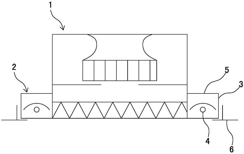
[0033] see figure 1 As shown, a fan filter unit includes a fan filter unit body 1, a lamp 2 is provided on the side of the fan filter unit body, and the power cord of the lamp is integrated with the power cord of the fan filter unit. Both sides of the body of the fan filter unit are symmetrically provided with lamps.

[0034] The main body of the fan filter unit and the lamp form a detachable connection structure.

[0035] The lamp includes a housing 3 and a lamp tube 4 arranged in the housing, and a window for replacing the lamp tube is provided on the top of the housing. A cover plate 5 is provided at the replacement window of the lamp tube.

[0036] The above-mentioned fan filter unit is installed in the ceiling grid 6 to be assembled into a clean room structure.


PUM


Abstract

The invention discloses a fan filter unit. The fan filter unit comprises a fan filter unit body. At least one side edge of the four side edges of the fan filter unit body is provided with lamps, and the power lines of the lamps are integrally arranged with a power line of the fan filter unit. The lamps are integrated with the fan filter unit to form a mechanism similar to a module, and thus circuits on the upper portion of a ceiling are greatly reduced, and the wiring difficulty is lowered.

Description

technical field [0001] The invention relates to a fan filter unit and a clean room. The fan filter unit is mainly used in clean rooms, clean workbenches, clean production lines, assembled clean rooms, local class 100 and the like. Background technique [0002] Fan filter unit, the English full name is FanFilterUnit, referred to as FFU. At present, FFU is widely used in clean rooms, clean benches, clean production lines, assembled clean rooms and local Class 100 applications. It can provide high-quality clean air for clean rooms and micro-environments of different sizes and cleanliness levels. [0003] FFU is equipped with primary and high-efficiency two-stage filters. The fan sucks air from the top of the FFU and filters it through the primary and high-efficiency filters. The filtered clean air is sent out at a uniform speed of 0.45M / S±20% on the entire air outlet surface. Suitable for obtaining a high level of cleanliness in various environments. In the renovation of ne...

Claims


Application Information

Patent Timeline
IPC IPC(8): F04D29/70F21V33/00
CPCF04D29/703F21V33/0096
Inventor 杨政谕
Owner L&K ENG SUZHOU
Learn More