Air conditioning equipment
A technology of air-conditioning equipment and air-conditioning internal unit, which is applied in the direction of air-conditioning systems, lighting and heating equipment, space heating and ventilation, etc. It can solve the problems of no practical function, difficulty in blowing down, and high installation position, so as to improve the performance of fans, The effect of increasing the air intake area and increasing the contact area
- Summary
- Abstract
- Description
- Claims
- Application Information
AI Technical Summary
Problems solved by technology
Method used
Image
Examples
Embodiment 1
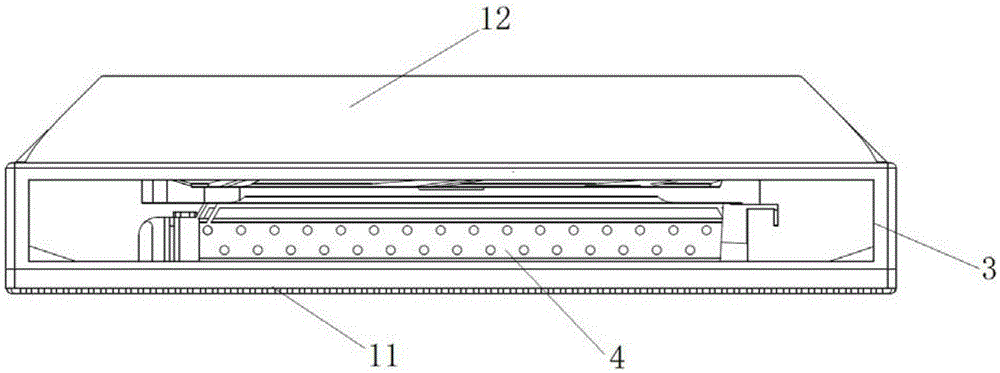
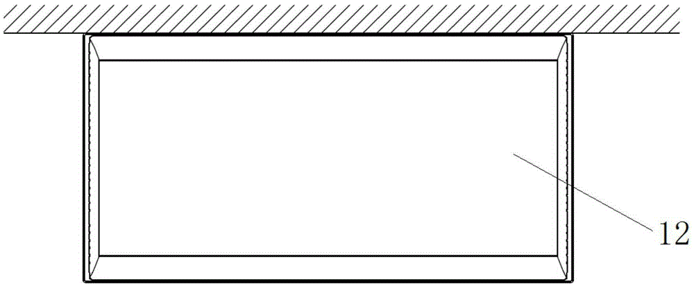
[0050] like Figure 1 to Figure 4 As shown, this embodiment provides an air conditioner, which includes an air conditioner inner unit. Specifically, the air conditioner inner unit includes a housing 1 , an air inlet 2 , and an air outlet 3 . Wherein, the air inlet 2 is arranged on the bottom 11 of the casing 1 . The air outlet 3 is provided on the side of the casing 1 . Wherein, the top 12 of the housing 1 is set in the shape of a table top, so that the indoor unit of the air conditioner in this embodiment can be used as a table.
[0051] The top, bottom and side parts mentioned in this embodiment or the following embodiments all refer to the relative positions of the internal air conditioner after the actual installation. By side is meant all side faces between the top and the side.
[0052] In this embodiment, by arranging the air inlet 2 at the bottom 11 of the inner casing 1 of the air conditioner, dust can be effectively prevented from accumulating on the air inlet of ...
Embodiment 2
[0056] Preferably, this embodiment provides an air conditioner, compared with the embodiment, such as Figure 4 , Figure 5 and Image 6 As shown, in this embodiment, the bottom 11 of the housing of the inner air conditioner is a plate-like structure. The air inlet 2 is arranged on the plate-like structure. Correspondingly, the air outlet (such as Figure 4 air outlet 31, Figure 5 air outlet 32, air outlet 33). When the air conditioner is working, the air in the room enters the air conditioner from the bottom 11 of the shell for heat exchange, and the air after heat exchange is blown into the room from the air outlet on the side of the shell.
[0057] Preferably, as Image 6As shown, there are a plurality of air inlets 2 , and the plurality of air inlets 2 are arranged on the plate-like structure 11 .
[0058] Preferably, as Image 6 As shown, a plurality of air inlets 2 are evenly arranged on the plate-like structure 11 in the form of a matrix.
[0059] In this embo...
Embodiment 3
[0061] Preferably, the present embodiment provides an air conditioner, compared with the above-mentioned embodiments, such as Figure 4 and Figure 5 As shown, the indoor unit of the air conditioner in this embodiment further includes a heat exchanger 4 and a fan assembly. Wherein, the heat exchanger 4 and the fan assembly are both arranged in the casing of the air conditioner inner unit. The heat exchanger 4 is used to perform heat exchange on the air entering the inner casing of the air conditioner from the air inlet 2; the fan assembly is used to perform work on the air after the heat exchanger The air after heat treatment is discharged from the air outlet on the inner casing of the air conditioner (such as Figure 4 air outlet 31, Figure 5 The air outlet 32 and the air outlet 33) in the room enter the room.
[0062] Preferably, the heat exchanger 4 in this embodiment is arranged at the inner bottom of the casing. Preferably, when the bottom 11 of the casing is a pl...
PUM
 Abstract
Description
Claims
Application Information
 - R&D
- Intellectual Property
- Life Sciences
- Materials
- Tech Scout
- Unparalleled Data Quality
- Higher Quality Content
- 60% Fewer Hallucinations
Browse by: Latest US Patents, China's latest patents, Technical Efficacy Thesaurus, Application Domain, Technology Topic, Popular Technical Reports.
© 2025 PatSnap. All rights reserved.Legal|Privacy policy|Modern Slavery Act Transparency Statement|Sitemap|About US| Contact US: help@patsnap.com


