
Disc type positioning spacer

A spacer and disk-shaped technology, which is applied in the field of disk-shaped positioning spacers, can solve problems such as low work efficiency, increased operation difficulty, and increased use cost, and achieves the effects of improving efficiency and safety, simple and convenient operation, and simple structure

Active Publication Date: 2016-03-09
WEIHAI MTI MINING EQUIP
View PDF5 Cites 4 Cited by
  • Summary
  • Abstract
  • Description
  • Claims
  • Application Information

AI Technical Summary

Problems solved by technology

The existing spacers have complex structures, difficult operation, and low work efficiency; moreover, most spacers need to use high-pressure gas storage tanks and various gases to inflate the spacers, so as to achieve the purpose of positioning the spacers in the blast hole The use of these high-pressure gas tanks and various gases will not only increase the difficulty of operation and increase the cost of use, but also cause major safety hazards in mine production during their storage, transportation and use

Method used


Image

  • Disc type positioning spacer
  • Disc type positioning spacer
  • Disc type positioning spacer

Examples


Embodiment Construction

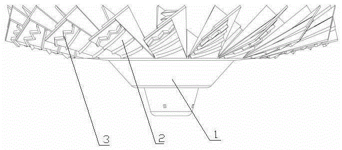
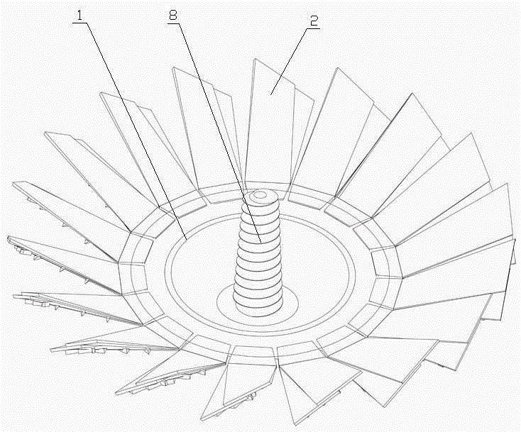
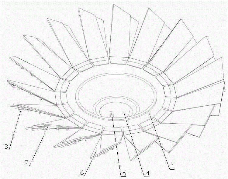
[0019] Such as Figure 1-4 The disc-shaped positioning spacer shown is provided with a baffle plate 1, and a connection hole 4 is provided on the upper side of the center of the baffle plate 1, and a fixed rod 8 perpendicular to the baffle plate is plugged into the connection hole 4, and the fixed rod 8 can move upwards and The connection holes 4 are separated, and elastic positioning flaps 2 are evenly distributed on the periphery of the retaining plate 1, the positioning flaps are fan-shaped or trapezoidal, and the lower side of the positioning flaps is provided with a sliding blocking strip 3. The inner end of the positioning wing 2 is fixedly connected to the baffle plate. The inner ends of the positioning wing are located on the same plane and connected in sequence. When the outer side of the positioning wing 2 is bent upward and the outer edge is at the same height, the two adjacent positioning wings Adjacent sides of the plates are abutted against or superimposed on eac...


PUM


Abstract

The invention discloses a disc type positioning spacer, and relates to the technical field of mine supplies. The disc type positioning spacer is provided with a baffle disc, the upper portion of the center of the baffle disc is provided with a connecting hole, a fixing rod is inserted into the connecting hole, the periphery of the baffle disc is evenly provided with elastic positioning wing plates, and the inner ends of the positioning wing plates are fixedly connected with the baffle disc; when the outer sides of the positioning wing plates are upwards bent and the outer edges of the positioning wing plates are located on the same plane, the adjacent edges of every two adjacent positioning wing plates abut against each other in an attached mode or are overlapped, and the positioning wing plates and the baffle disc form a spacer disc which takes the connecting hole as the center. The disc type positioning spacer has the advantages of being simple in structure, easy to operate, high in efficiency, safe in usage, capable of saving energy, general in dry hole and water hole and the like.

Description

technical field [0001] The invention relates to the technical field of mining supplies, and in detail is a disc-shaped positioning spacer with simple structure, easy operation, safe use, energy saving and low application cost. Background technique [0002] We know that in the deep hole blasting of blasting engineering, in order to achieve the purpose of reducing the foundation, reducing the explosion pressure in the blast hole, expanding the range of the rupture zone, and improving the effective utilization rate of explosive blasting energy, thereby reducing the unit consumption of explosives, usually in blasting A spacer is used for spaced charge in the blast hole with a hole diameter of more than 90 mm and a hole depth of more than 10 meters. The existing spacers have complex structures, difficult operation, and low work efficiency; moreover, most of the spacers need to use high-pressure gas storage tanks and various gases to inflate the spacers, so as to achieve the purpo...

Claims


Application Information

Patent Timeline
Patent Type & Authority Applications(China)
IPC IPC(8): F42D1/08
CPCF42D1/08
Inventor 刘洪波
Owner WEIHAI MTI MINING EQUIP
Learn More