Multiple Grating Scribes Parallel Interference Controlled Grating Scribing Method

A grating knife and grating scribing technology, applied in the directions of diffraction gratings, optics, optical components, etc., can solve the problems of difficult to achieve precise scribing of large-sized gratings above the meter level, low grating scribing efficiency, etc., and save grating scribing. The effect of reducing the scribing time, improving the grating scribing efficiency, and suppressing the relative rotation angle error

Active Publication Date: 2018-06-26
CHANGCHUN INST OF OPTICS FINE MECHANICS & PHYSICS CHINESE ACAD OF SCI
View PDF6 Cites 0 Cited by
  • Summary
  • Abstract
  • Description
  • Claims
  • Application Information

AI Technical Summary

Problems solved by technology

[0004] The purpose of the present invention is to propose a parallel interference control type grating scoring method with multiple grating scribers, so as to solve the problems in the prior art that it is difficult to realize the precise marking of a large-scale grating above the meter level and the low efficiency of grating marking

Method used


Image

  • Multiple Grating Scribes Parallel Interference Controlled Grating Scribing Method
  • Multiple Grating Scribes Parallel Interference Controlled Grating Scribing Method
  • Multiple Grating Scribes Parallel Interference Controlled Grating Scribing Method

Examples


Embodiment 1

[0050] The multiple grating cutter parallel interference control type grating marking method of the present invention comprises the following steps:

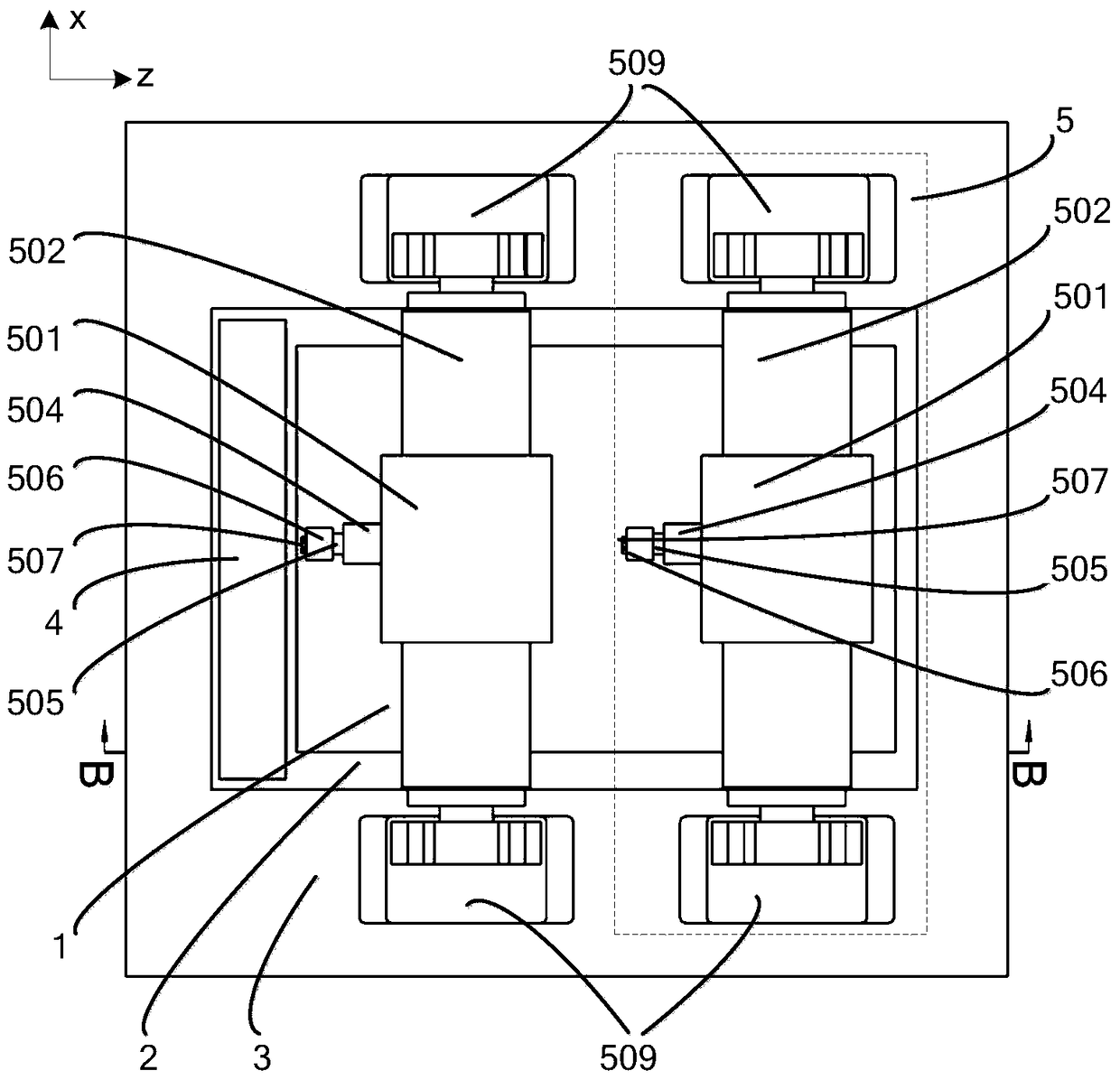
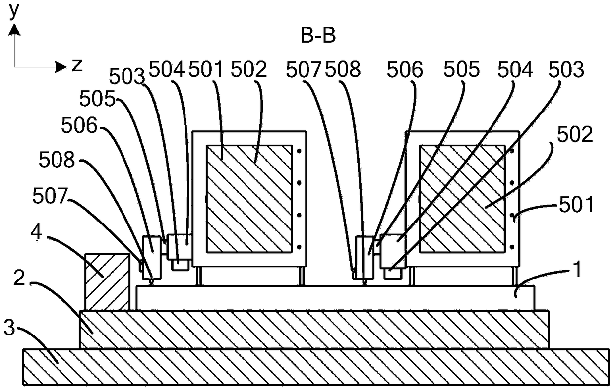
[0051] Step 1: Install two sets of scoring systems 5 in parallel on the main base 3 at a distance of 400 mm, and each set of scoring systems 5 is equipped with a piezoelectric actuator 505, a position measurement interferometer 503 and a reference reflector on the scoring tool holder 506 mirror 507;

[0052] Step 2: install the grating substrate used for the grating blade turning experiment on the grating substrate carrying table 2, and perform the blade turning experiment on the grating cutter 508 in the 2 sets of marking systems 5;

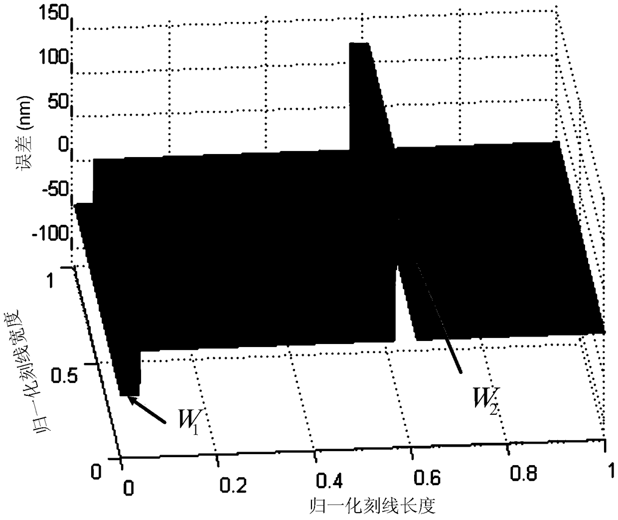
[0053] Step 3: Install the grating substrate used for the grating pre-scribing experiment on the grating substrate carrying workbench 2, conduct the grating pre-scribing experiment, and obtain the position error E of the second sub-grating relative to the first sub-grating 2 ;

[0054] Step 4: A...

Embodiment 2

[0077] The difference between this embodiment and Embodiment 1 is that: the measuring reflector 4 is two pieces, the first measuring reflector 4 is arranged at the end of the grating base bearing workbench 2, and the second measuring reflector 4 is respectively arranged at the second On the scribing tool holder 506 of one set of scribing system 5, the position measurement interferometer 503 in the first set of scribing system 5 measures the distance between the corresponding reference mirror 507 and the measuring mirror 4 on the grating substrate carrying workbench. The position measurement interferometer 503 in the second marking system 5 measures the relative position between its corresponding reference mirror 507 and the measuring mirror 4 set on the first marking system 5 . Except that the length of the first measuring reflector 4 is slightly longer than the length of the grating lines, the other measuring reflectors 4 are relatively small in size, and the size is ≥5mm×5mm....


PUM


Abstract

The invention relates to a parallel interference-controlled grating marking method of multiple grating scribers, which belongs to the field of plane diffraction grating production, and aims to solve the problems in the prior art that it is difficult to achieve precise marking of large-scale gratings above the meter level and the grating marking efficiency is low. The following steps of the present invention are as follows: Step 1: Install n sets of marking systems in parallel on the main base with an equal distance D; Step 2: Install the grating substrate used for the grating turning edge experiment on the grating substrate carrying workbench, for n Set the grating cutter in the scoring system to perform the blade turning experiment; Step 3: install the grating substrate used for the grating pre-scribing experiment on the grating substrate carrying workbench, carry out the grating pre-scribing experiment, and obtain the second to nth The engraved line position error E2, E3...En of each sub-grating relative to the first sub-grating; Step 4: According to the engraved position of the 2nd to nth sub-gratings relative to the first sub-grating obtained in step 3 Errors E2, E3...En carry out the marking of the grating master board.

Description

technical field [0001] The invention belongs to the field of making mechanically scribed plane diffraction gratings, and in particular relates to a parallel interference control type grating scribing method of a plurality of grating cutters. Background technique [0002] The mechanical scribing method is one of the main methods to make planar diffraction gratings. This method generally works in the Roland working mode, that is, the marking system drives the grating cutter to perform reciprocating motion, and the indexing system drives the grating substrate carrying table to perform unidirectional feed motion. The function of the grating cutter is to extrude grating lines with fixed spacing on the aluminum film of the grating substrate. [0003] The existing grating mechanical scribing method only uses a single grating knife to realize the scribing of the entire grating, which mainly has the following two disadvantages: 1) After the grating scribing exceeds a certain scribin...

Claims


Application Information

Patent Timeline
Patent Type & Authority Patents(China)
IPC IPC(8): G02B5/18
CPCG02B5/1852
Inventor 李晓天卢禹先于海利唐玉国马振予齐向东糜小涛于宏柱张善文巴音贺希格
Owner CHANGCHUN INST OF OPTICS FINE MECHANICS & PHYSICS CHINESE ACAD OF SCI
Why Eureka
Try Eureka