A switch with power failure protection function

A technology of power failure protection and function, applied in the direction of electrical switches, circuits, electrical components, etc., can solve the problem of continuous connection of switches

Active Publication Date: 2018-09-28
ZHANGJIAGANG HUAJIE ELECTRONICS
View PDF4 Cites 0 Cited by
  • Summary
  • Abstract
  • Description
  • Claims
  • Application Information

AI Technical Summary

Problems solved by technology

[0003] The technical problem to be solved by the present invention is to provide a switch with a power failure protection function. The switch has a power failure protection function. There are security risks in connectivity

Method used


Image

  • A switch with power failure protection function
  • A switch with power failure protection function
  • A switch with power failure protection function

Examples


Embodiment Construction

[0029] The switch with power failure protection function according to the present invention will be further described in detail through specific embodiments below.

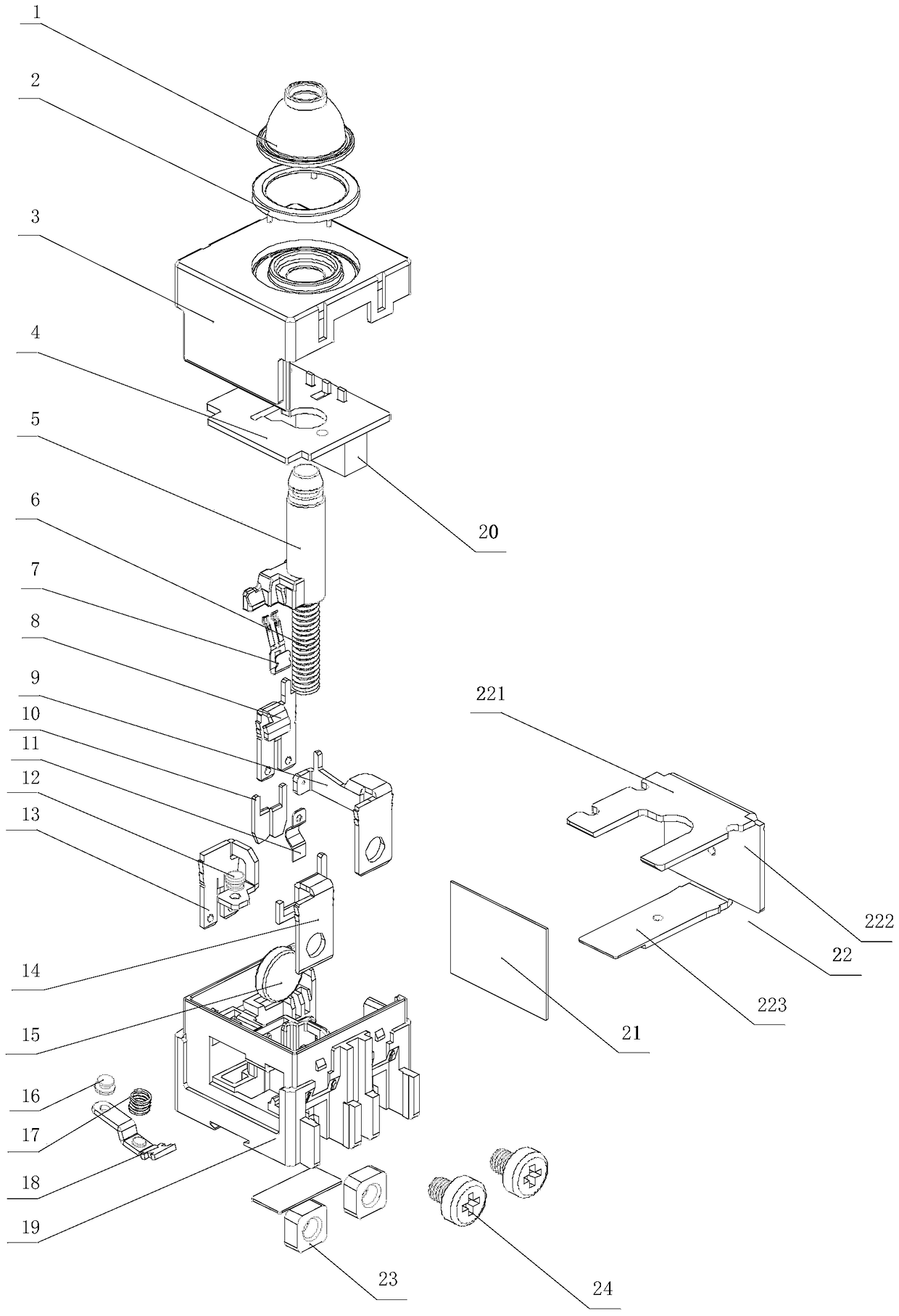
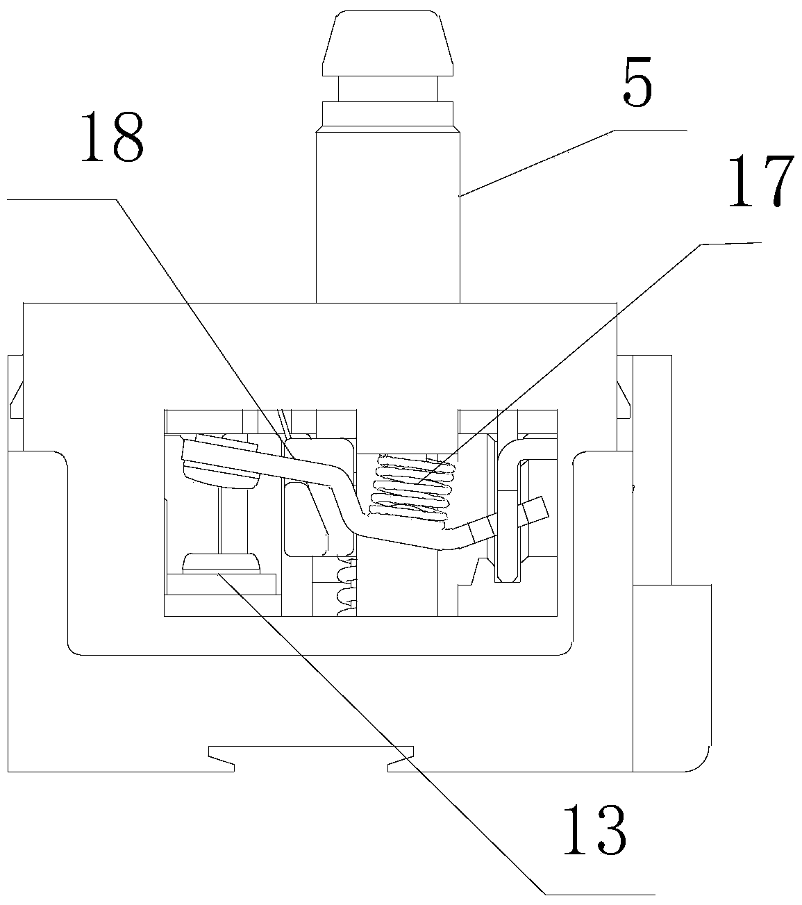
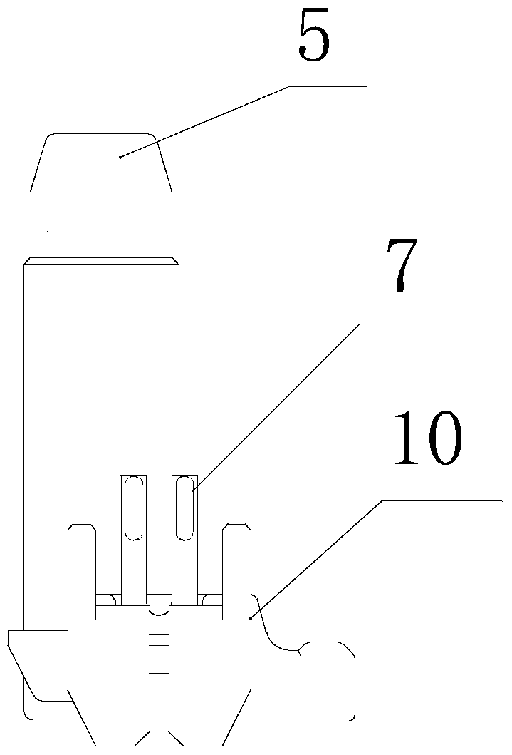
[0030] Such as Figure 1-11As shown, a switch with a power failure protection function includes a cover plate 3 and a base 19 fixed to each other. The base 19 is provided with a terminal 23, and the base 19 is fixed with a first static contact 13 and a first moving contact. A frame 14, a circuit board 4 is arranged between the cover plate 3 and the base 19, a thyristor 20 is welded on the circuit board 4, and the first moving contact frame 14 is welded to the power supply end of the circuit board 4, so The first static contact 13 is provided with a static contact 12, and the first movable contact frame 14 is swingably equipped with a movable contact 18. One end of the movable contact 18 is a contact end and the other end is a mounting end. The mounting end of the moving contact 18 is installed on the first moving...


PUM


Abstract

The invention discloses a switch capable of power failure protection. The switch comprises a cover plate, a pedestal, a first static contact, a first moving contact rack, a circuit board and a silicon controlled rectifier, the first moving contact rack is welded to the power supply end of the circuit board, a moving contact is mounted on the first moving contact rack in a swinging manner, one end of the moving contact is a contact end, the other end of the moving contact is an installation end, the installation end of the moving contact is mounted on the first moving contact rack, and a moving contact spring is arranged between the moving contact and the pedestal. The switch further comprises a push rod, a return spring is arranged between the lower end of the push rod and the pedestal, the push rod is provided with a supporting part, and in the closed state, the supporting part supports the moving contact upwardly so that the contact end of the moving contact is separated from the static contact. Two signal collection springs are welded to the signal collection point of the circuit board, a sliding contact sheet is fixed to the push rod, and the sliding contact sheet and the signal collection springs are connected before or after that the moving contact make contact with the static contact. The switch can be used to solve the safety problem in power supply after sudden power failure of an operator.

Description

technical field [0001] The invention relates to the field of electronic switches, in particular to a switch with a power failure protection function. Background technique [0002] Existing switches for electric drills or angle grinders do not include a power failure protection function, and include mutually fixed cover plates, bases and push rods, the base is provided with binding posts, and the base is fixed with the first static contact and the first moving contact frame , a circuit board is arranged between the cover plate and the base, a silicon controlled rectifier is welded on the circuit board, the first moving contact frame is welded to the power supply end of the circuit board, a static contact is arranged on the first static contact, and a static contact is arranged on the first moving contact A moving contact is installed swinging on the frame. One end of the moving contact is the contact end and the other end is the installation end. The installation end of the m...

Claims


Application Information

Patent Timeline
Patent Type & Authority Patents(China)
IPC IPC(8): H01H1/58H01H3/32H01H9/52
CPCH01H1/5805H01H3/32H01H9/52
Inventor 田昊凌虎明
Owner ZHANGJIAGANG HUAJIE ELECTRONICS
Why Eureka
Try Eureka