A safe sodium-sulfur battery

A sodium-sulfur battery, a safe technology, applied in the direction of secondary batteries, battery pack components, battery boxes/coatings, etc., can solve the problems of active material leakage, unsafe structure, etc., to ensure battery safety, discharge speed and depth favorable , Avoid the effect of the battery temperature rising too fast

Active Publication Date: 2018-01-12
东方电气洁能科技成都有限公司
View PDF16 Cites 0 Cited by
  • Summary
  • Abstract
  • Description
  • Claims
  • Application Information

AI Technical Summary

Problems solved by technology

[0007] The present invention aims to solve the problem of unsafe structure in the prior art where the container for storing metal sodium is placed inside the ceramic tube in the battery, and provides a safe sodium-sulfur battery, so that when the ceramic tube inside the battery is damaged, the Possibility of instantaneous violent reaction between metal sodium and sulfur, keeping the battery exterior intact, avoiding active material leakage and fire

Method used


Image

  • A safe sodium-sulfur battery
  • A safe sodium-sulfur battery
  • A safe sodium-sulfur battery

Examples


Embodiment 1

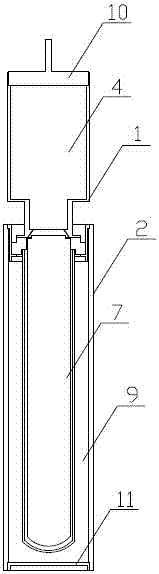
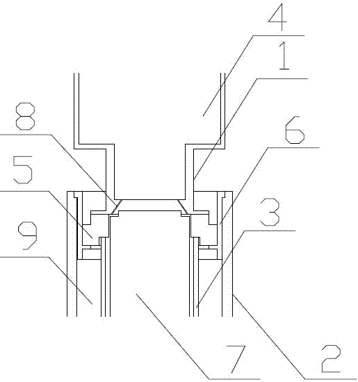
[0023] A safe sodium-sulfur battery, comprising a sodium storage tank 1, a battery casing 2, and a solid electrolyte ceramic tube 3, wherein metal sodium 4 is stored in the sodium storage tank 1, and an insulating ceramic ring 5 is connected to the bottom of the sodium storage tank 1 , the bottom of the insulating ceramic ring 5 is connected to the top of the solid electrolyte ceramic tube 3, and the outer wall of the insulating ceramic ring 5 is connected to the inner wall of the battery case 2 through a metal connector 6; the solid electrolyte ceramic tube 3 The inside of the negative electrode current collector 7 is provided with the top of the negative electrode current collector 7 connected to the sodium storage tank 1; the bottom of the sodium storage tank 1 is provided with an inclined aperture channel 8, and the sodium storage tank 1 The inner metal sodium 4 communicates with the gap between the solid electrolyte ceramic tube 3 and the negative electrode current collect...

Embodiment 2

[0026] On the basis of embodiment 1:

[0027] Preferably, the width of the gap between the solid electrolyte ceramic tube 3 and the negative electrode collector 7 is 0.5 mm.

[0028] Preferably, the top of the sodium storage tank 1 is provided with a battery top cover 10 for sealing the sodium metal 4 .

[0029] Preferably or further, the bottom of the battery casing 2 is provided with a battery bottom cover 11 for sealing the sulfur electrode 9 .

[0030] Preferably, the upper end of the solid electrolyte ceramic tube 3 is open, and the lower end is a sealed round or flat bottom.

Embodiment 3

[0032] On the basis of embodiment 1:

[0033] Preferably, the width of the gap between the solid electrolyte ceramic tube 3 and the negative electrode collector 7 is 3mm.

[0034] Preferably, the top of the sodium storage tank 1 is provided with a battery top cover 10 for sealing the sodium metal 4 .

[0035] Preferably or further, the bottom of the battery casing 2 is provided with a battery bottom cover 11 for sealing the sulfur electrode 9 .

[0036] Preferably, the upper end of the solid electrolyte ceramic tube 3 is open, and the lower end is a sealed round or flat bottom.


PUM

PropertyMeasurementUnit
widthaaaaaaaaaa

Abstract

The invention relates to a safe sodium-sulfur battery, belonging to the technical field of energy storage batteries. Metal sodium is stored in the sodium storage tank of the battery of the present invention, the bottom of the sodium storage tank is connected to an insulating ceramic ring, the bottom of the insulating ceramic ring is connected to the top of the solid electrolyte ceramic tube, and the outer wall of the insulating ceramic ring is It is connected with the inner wall of the battery case through a metal connector. The sodium storage tank of the present invention is arranged above the solid electrolyte ceramic tube, so that when the ceramic tube inside the battery is damaged, the possibility of instantaneous violent reaction between metallic sodium and sulfur can be reduced, the exterior of the battery can be kept intact, and active material leakage and ignition can be avoided.

Description

technical field [0001] The invention relates to a battery, more specifically, the invention relates to a safe sodium-sulfur battery, which belongs to the technical field of energy storage batteries. Background technique [0002] Sodium-sulfur batteries have been regarded as one of the technologies for large-scale electrochemical energy storage due to their high energy density, long service life, and abundant raw materials. focus on. The safety of sodium-sulfur batteries is an issue that has received much attention and needs to be further improved during the development of its large-scale industry. The safety of sodium-sulfur batteries needs to be improved by improving the safety of single batteries and the design and control methods of modules and energy storage systems. Among them, the safety of single batteries is a crucial factor affecting the safety of energy storage systems. The main active materials of sodium-sulfur batteries are metallic sodium and elemental sulfur....

Claims


Application Information

Patent Timeline
Patent Type & Authority Patents(China)
IPC IPC(8): H01M10/39H01M10/38H01M2/02H01M2/04H01M50/107H01M50/152
CPCH01M10/38H01M10/3909H01M50/138H01M50/1535Y02E60/10Y02P70/50
Inventor 林久唐光盛朱睿
Owner 东方电气洁能科技成都有限公司
Why Eureka
Try Eureka