Interference coordination method and device
An interference coordination and interference technology, applied in the field of communication, can solve the problems of heavy network signaling load and high complexity
- Summary
- Abstract
- Description
- Claims
- Application Information
AI Technical Summary
Problems solved by technology
Method used
Image


Examples
Embodiment 1
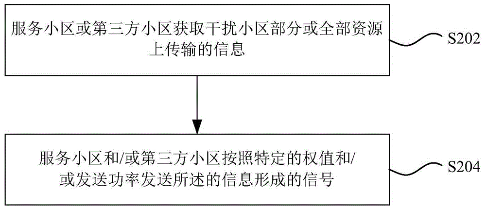
[0137] In this embodiment, part of the power of the serving cell is sacrificed for interference cancellation, which may reduce the transmission power of useful signals. In order not to affect the transmission of useful signals, a third-party cell can assist in reducing interference. Here The third-party cell may be a cell with no service, or a cell with idle corresponding resources. When the third cell is an idle cell and is not activated, the node where the central control unit is located, the macro cell or the serving cell activates the third cell.
[0138] Such as Image 6 As shown, when cell#1 sends a signal to its user UE#1-2, it will cause serious interference to UE#2-1 of cell#2. At this time, cell#2 is a victim cell, and UE#2-1 is a victimUE; In order to reduce the interference to UE#2-1, the third-party cell sends an interference cancellation signal w at a certain power 3,1,2,1 S 1, on the UE#2-1 side, the simultaneous transmission weight and power setting on the U...
Embodiment 2
[0154] In this embodiment, a transmission method is given in which the serving cell allocates part of the power for interference cancellation, such as Figure 14As shown, when cell#1 performs downlink transmission, it will cause interference to UE#2-1 in cell#2. At this time, cell#2 is the victim cell, UE#2-1 is the victimUE; the downlink transmission signal of cell#1 The interference to UE#2_1 can be characterized as ρ 1 h 1,2,1 w 2,1,1,1 S 1 , the target signal of UE#2-1 is ρ 2b h 1,2,2 w 1,2,2,2 S 2 , in order to overcome the interference of cell#1 to UE#2-1 without affecting the downlink transmission performance of cell#1, in this embodiment, cell#1 passes the downlink transmission signal through backhaul (such as X2 interface, wireless backhaul, etc.) Share its signal with cell#2, cell#2 sacrifices part of the power to send the same signal as cell#1, and design weights to ensure that the signal sent by cell#1 and the same signal sent by cell#2 are in UE#2-1 sides ...
Embodiment 3
[0167] In the implementation manners described in the first and second embodiments, the user equipment needs to feed back the weight information used for interference cancellation and the transmission power information of the interference cancellation signal. In an implementation of this embodiment, the user equipment is configured according to one or more sets of measurement reference signals or process channel information measured by the network side, interfering cell multi-antenna precoding weight indication information, and measurement reference signal or process corresponding Calculate the interference cancellation weight and / or power based on the identification information. Specifically, it is assumed that the channel matrix of the measured interfering cell is characterized by H I , the precoding matrix of the interfering cell is w I The corresponding rank is Rank I , and the signal transmission power is ρ I ; The channel matrix of the third-party cell (or serving cel...
PUM
 Abstract
Description
Claims
Application Information
 - R&D
- Intellectual Property
- Life Sciences
- Materials
- Tech Scout
- Unparalleled Data Quality
- Higher Quality Content
- 60% Fewer Hallucinations
Browse by: Latest US Patents, China's latest patents, Technical Efficacy Thesaurus, Application Domain, Technology Topic, Popular Technical Reports.
© 2025 PatSnap. All rights reserved.Legal|Privacy policy|Modern Slavery Act Transparency Statement|Sitemap|About US| Contact US: help@patsnap.com