System and method for detecting tissue and fiber tract deformation

A tissue change and tissue technology, which is applied in systems and fields for detecting tissue and fiber bundle deformation, can solve the problems that the complexity associated with tissue displacement cannot be well solved, etc.

Inactive Publication Date: 2016-03-09
SYNAPTIVE MEDICAL (BARBADOS) INC
View PDF0 Cites 6 Cited by
  • Summary
  • Abstract
  • Description
  • Claims
  • Application Information

AI Technical Summary

Problems solved by technology

Although much of the following discussion uses surgical procedures in the brain as an example, similar problems arise in surgery on the spine and other orthopedic applications and the techniques are generally applicable
[0008] The complexities associated with tissue displacement that occurs during surgery are not well addressed by currently available systems and methods

Method used


Image

  • System and method for detecting tissue and fiber tract deformation
  • System and method for detecting tissue and fiber tract deformation
  • System and method for detecting tissue and fiber tract deformation

Examples


example

[0119] Example: Medical Procedures Involving the Brain

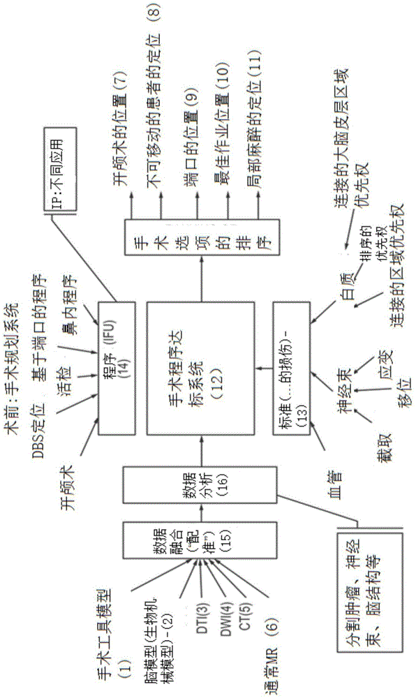
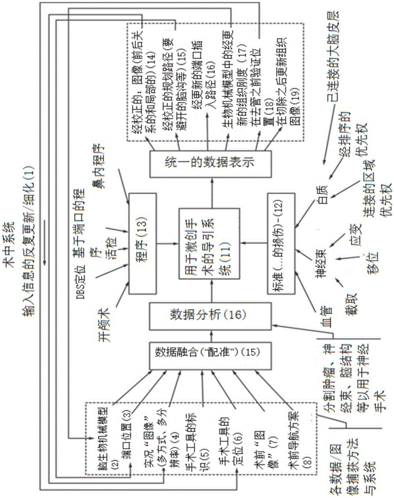
[0120] Figure 6 A flowchart illustrating the present method of modeling fiber bundle deformation comprising a DTI image and a surgical tool shape model. Figure 6 is an implementation for the specific case of only generating a fiber bundle deformation model and does not involve Figure 5 other tissue types as described in . exist Figure 6 , two data streams (comprising DTI image data (step 302) and tool shape model (step 310)) are received as input data.

[0121] After receiving the DTI image set data (step 302), the system then preprocesses the data (step 304), typically using streamline tractography algorithms. After preprocessing (step 304), a fiber bundle map is created (step 306). A tissue model is then generated (step 308) using the fiber tract map generated in step 306.

[0122] Figure 7 for further elaboration Figure 6 A flowchart of the "Create Organizational Model" step (308) outlined in , with deta...


PUM


Abstract

Disclosed herein is a method for producing an evolvable tissue model of a patient and, using this model, modelling physical transformations of the tissue (e.g. deformation) of the tissue model by interacting the tissue model with influence models which model interactions with the tissue such as surgical instruments, pressure, swelling, temperature changes etc. The model is produced from a set of input data of the tissue which includes directional information of the tissue. The directional information is used to produce an oriented tissue map. A tissue model is then produced from the oriented tissue map such that the tissue model reflects the directionality of the tissue component. When the tissue model is subjected to an influence that causes tissue deformation over a period of time, the tissue model directionally deforms over the period of time in a manner which reflects a trajectory of the influence interacting with the directionality of the tissue component.

Description

[0001] Cross References to Related Applications [0002] This application claims priority to U.S. Provisional Application No. 61 / 799,921, filed March 15, 2013, entitled "SYSTEM AND METHODS FOR DETECTING TISSUE AND FIBRE TRACT DEFORMATION," the entire contents of said U.S. Provisional Application Incorporated herein by reference. [0003] This application claims priority to US Provisional Application No. 61 / 800,787, filed March 15, 2013, entitled "POLARIZEDLIGHTMAGING DEVICE," which is incorporated herein by reference in its entirety. [0004] This application claims priority to U.S. Provisional Application No. 61 / 800,155, filed March 15, 2013, entitled "PLANNING, NAVIGATION AND SIMULATION SYSTEMS AND METHODS FORMINIMALLY INVASIVE THERAPY," said U.S. Provisional The entire content of the application is incorporated herein by reference. [0005] This application claims priority to U.S. Provisional Application No. 61 / 924,993, filed January 8, 2014, entitled "PLANNING, NAVIGATION ...

Claims


Application Information

Patent Timeline
Patent Type & Authority Applications(China)
IPC IPC(8): A61B34/20A61B5/00G06F19/00G09B23/28A61B5/055A61B6/03A61B8/13
CPCA61B5/055A61B5/0066G09B23/30A61B90/11A61B34/10A61B2034/105G06T7/0012G06T2207/30012
Inventor 盖尔·西拉西蒙·亚历山大卡梅伦·皮龙乔舒亚·里士满麦克尔·伍德穆鲁加斯·尤瓦拉吉戴维·盖洛普韦斯·雷奇斯门罗·M·托马斯
Owner SYNAPTIVE MEDICAL (BARBADOS) INC
Why Eureka
Try Eureka