Loader and retriever for transcatheter heart valve, and methods of crimping transcatheter heart valve

a technology of transcatheter heart valve and retriever, which is applied in the field of medical devices, can solve the problems of limited research directed to whether the devices and techniques used to crimp replacement valves can be realized without, and the procedure is very invasive and complicated, so as to simplify the valve introduction process and improve the operation of the valve. , the effect of improving the operation efficiency

Active Publication Date: 2017-02-23
EDWARDS LIFESCIENCES CORP
View PDF5 Cites 8 Cited by
  • Summary
  • Abstract
  • Description
  • Claims
  • Application Information

AI Technical Summary

Benefits of technology

[0010]Features of the invention are directed to a loader tube and assembly for a transcatheter delivery system, where a crimped transcatheter heart valve can be loaded into a delivery sheath, and can be retrieved from the delivery sheath and removed from a patient's body without removing the delivery sheath from the access site. Other features of the invention are directed to an assembly and method for more easily facilitated crimping of a transcatheter heart valve prior to loading the replacement valve into the delivery sheath. Still other features of the invention are directed to devices and methods for more effectively crimping a transcatheter heart valve prior to delivery of the replacement valve in order to reduce shrinkage or other deformation or damage that can occur to the leaflet tissue of the valve, and to improve effectiveness of valve operation or functionality after implantation.
[0015]According to embodiments of the invention, transcatheter heart valves can more easily and effectively be introduced into an existing delivery sheath system, where the replacement valve can further be retrieved from the delivery sheath system in a more efficient manner. Furthermore, embodiments of the invention can simplify the valve introduction process for a practitioner or other end user, and can also improve operation of the valve once it has been implanted in a patient. According to other embodiments, transcatheter heart valves can be stored in a more effective and efficient manner, to reduce deformation or other damage to the heart valves and to simplify end user requirements.

Problems solved by technology

Such procedures were very invasive and complicated, and also required lengthy recovery periods for the patients.
However, there has been limited research directed to whether the devices and techniques used to crimp the replacement valves can be realized without damaging the tissue leaflets, or reducing or compromising other functionality of the replacement valves after the valves have been expanded at the implant sites.
There has been little research, however, into how to more effectively introduce a prosthetic replacement valve and / or delivery system into the above-described sheath systems.
Furthermore, there has been limited research into different devices and / or methods that can be used in conjunction with the existing expandable sheath systems, to further ease or simplify the delivery or implantation process, or to deal with other issues that can arise during valve delivery.

Method used


Image

  • Loader and retriever for transcatheter heart valve, and methods of crimping transcatheter heart valve
  • Loader and retriever for transcatheter heart valve, and methods of crimping transcatheter heart valve
  • Loader and retriever for transcatheter heart valve, and methods of crimping transcatheter heart valve

Examples


first embodiment

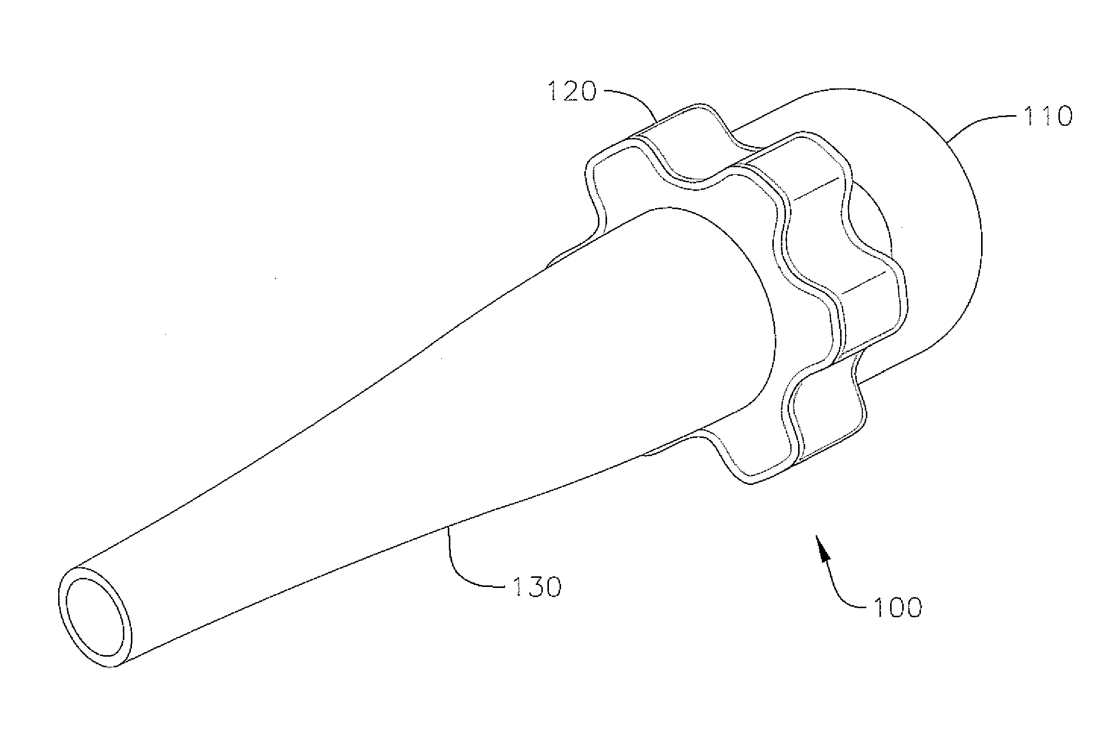
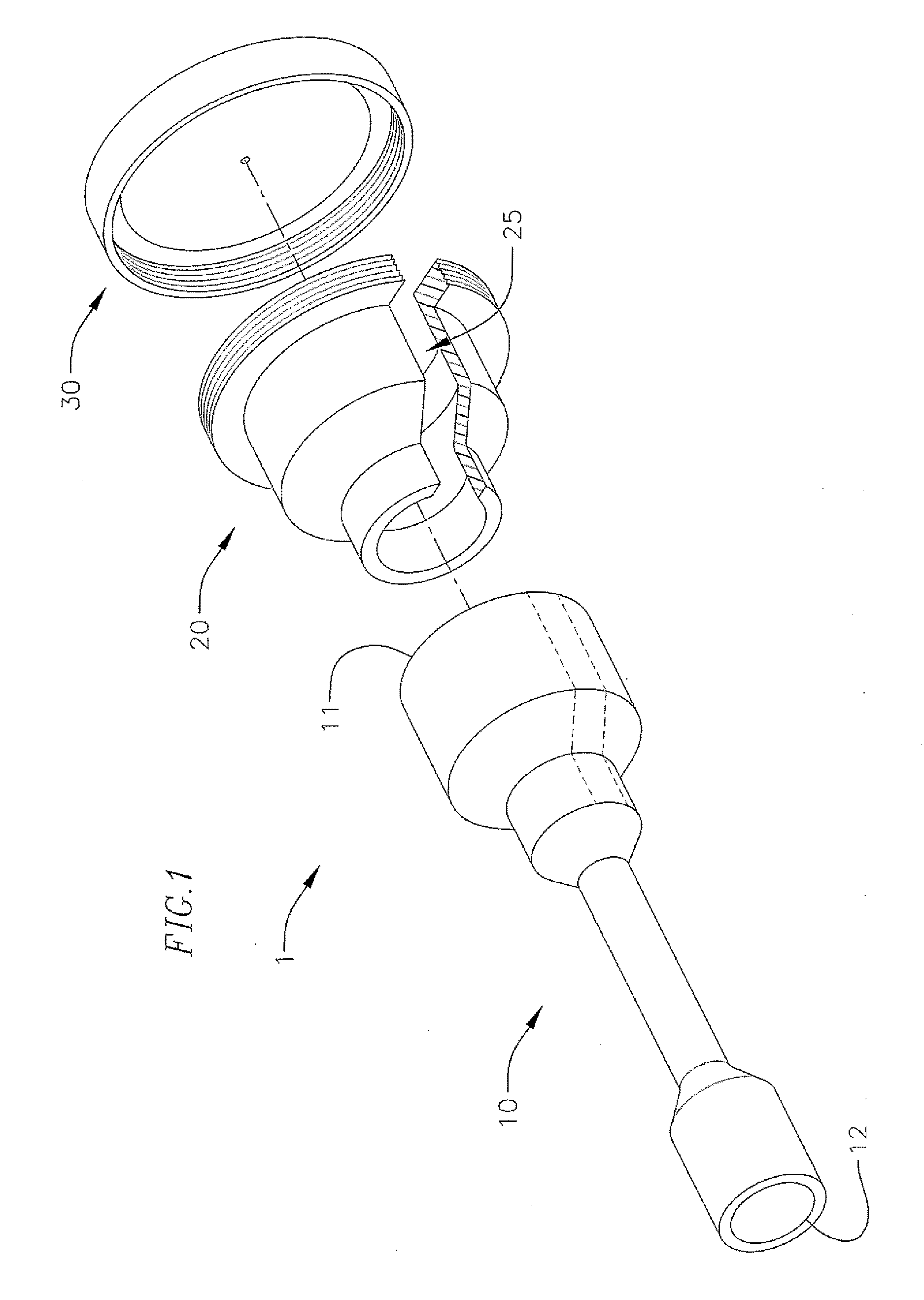
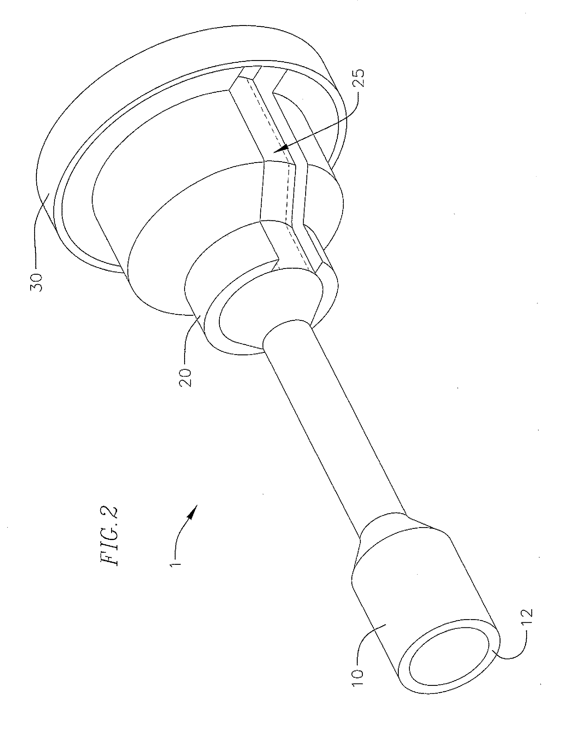
[0045]FIG. 6 shows a cross-sectional view of an assembled loader assembly 1 according to the As can be seen in FIG. 6, the hub 20 is bonded or otherwise attached to the proximal section 15 of the loader tube 10, where the inner wall of the hub 20 substantially corresponds to the outer wall of the proximal section 15 of the loader tube 10. The distal end 22 of the hub 20 is axially aligned with the circumferential trail of score marks 18b extending around the loader tube 10. Additionally, as can best be seen in FIG. 2, the slot 25 of the hub 20 is aligned with the two lines of score marks 18a, so that the score marks 18a are exposed to the outside of the loader assembly 1 through the slot 25. Additionally, the cap 30 is attached to the proximal end 21 of the hub 20. As indicated above, the cap 30 includes a seal 36, which can facilitate hemostasis through loader assembly 1 during a surgical or other medical procedure. Other seals (not shown) can also be arranged through the loader t...

second embodiment

[0061]Referring to FIGS. 12-22, a loader assembly for loading a THV will be described. Similar to the loader assembly discussed with respect to FIGS. 1-11, the loader assembly in FIGS. 12-22 is generally configured for use with heart valve prostheses that can be radially crimped to facilitate endovascular delivery to an implant site at a patient's heart. The loader assembly can be used to more easily and efficiently load the crimped valve into a patient's body through a delivery sheath device or system. However, in the embodiment in FIGS. 12-22, the replacement valve can be crimped directly on a balloon expander prior to insertion into the delivery sheath and before the balloon expander has been inflated, where the crimped prosthetic valve and balloon delivery system can be inserted into the delivery sheath at the access site of the patient, and then advanced to the implant site together.

[0062]Generally, prior to inserting a valve prosthesis into the patient's body, the valve is ret...


PUM

PropertyMeasurementUnit
shrinkageaaaaaaaaaa
diameteraaaaaaaaaa
widthaaaaaaaaaa

Abstract

A loader and method for loading a transcatheter heart valve into a delivery sheath or catheter is described that is also configured to facilitate retrieval of the heart valve back through the delivery sheath while protecting the delivery sheath from damage. Another loader provides for easier crimping and loading of a THV into a delivery sheath or catheter from a storage jar or container. A method for crimping a THV facilitates easier end user preparation of the valve for implantation and reduces the likelihood of tissue deformation in the valve during storage. These devices and methods for deploying THVs simplify the valve replacement procedure.

Description

CROSS-REFERENCE TO RELATED APPLICATION(S)[0001]The present application claims priority to and the benefit of U.S. Provisional Patent Application Ser. No. 62 / 207,879, filed Aug. 20, 2015, the contents of which are hereby incorporated by reference in their entirety.BACKGROUND[0002]Field[0003]The invention generally relates to medical devices and procedures associated with transcatheter prosthetic heart valves that are employed to replace diseased heart valves. Embodiments include devices for loading a transcatheter heart valve into a delivery sheath, and for facilitating retrieval of the heart valve through a hub of the delivery sheath. Other embodiments include devices and methods for easier crimping of the valve prior to loading into a delivery sheath.[0004]Description of Related Art[0005]Prosthetic heart valves that can be delivered percutaneously or less invasively, compared to being implanted via open heart surgery, have gained popularity in recent years, and research and develop...

Claims


Application Information

Patent Timeline
Patent Type & Authority Applications(United States)
IPC IPC(8): A61F2/24B21D39/04A61F2/00
CPCA61F2/2433B21D39/048A61F2/0095A61F2/2412A61F2/95A61F2/2436A61F2250/0039A61F2/9522
Inventor METCHIK, ASHER L.NGUYEN, THANH V.BIRAN, RAZCHANG, ARVIN T.NAGPURWALA, TARANUMLINDSTROM, JEFF
Owner EDWARDS LIFESCIENCES CORP
Why Eureka
Try Eureka