Coherent Optical Receiver

A coherent light and receiver technology, applied in electromagnetic receivers, digital transmission systems, electrical components, etc., can solve problems such as the failure of clock extraction with higher ROF values, and achieve the effect of improving accuracy

Active Publication Date: 2019-06-18
HUAWEI TECH CO LTD
View PDF8 Cites 0 Cited by
  • Summary
  • Abstract
  • Description
  • Claims
  • Application Information

AI Technical Summary

Problems solved by technology

It achieves clock extraction for small ROF values ​​but fails for higher ROF values

Method used


Image

  • Coherent Optical Receiver
  • Coherent Optical Receiver
  • Coherent Optical Receiver

Examples


Embodiment Construction

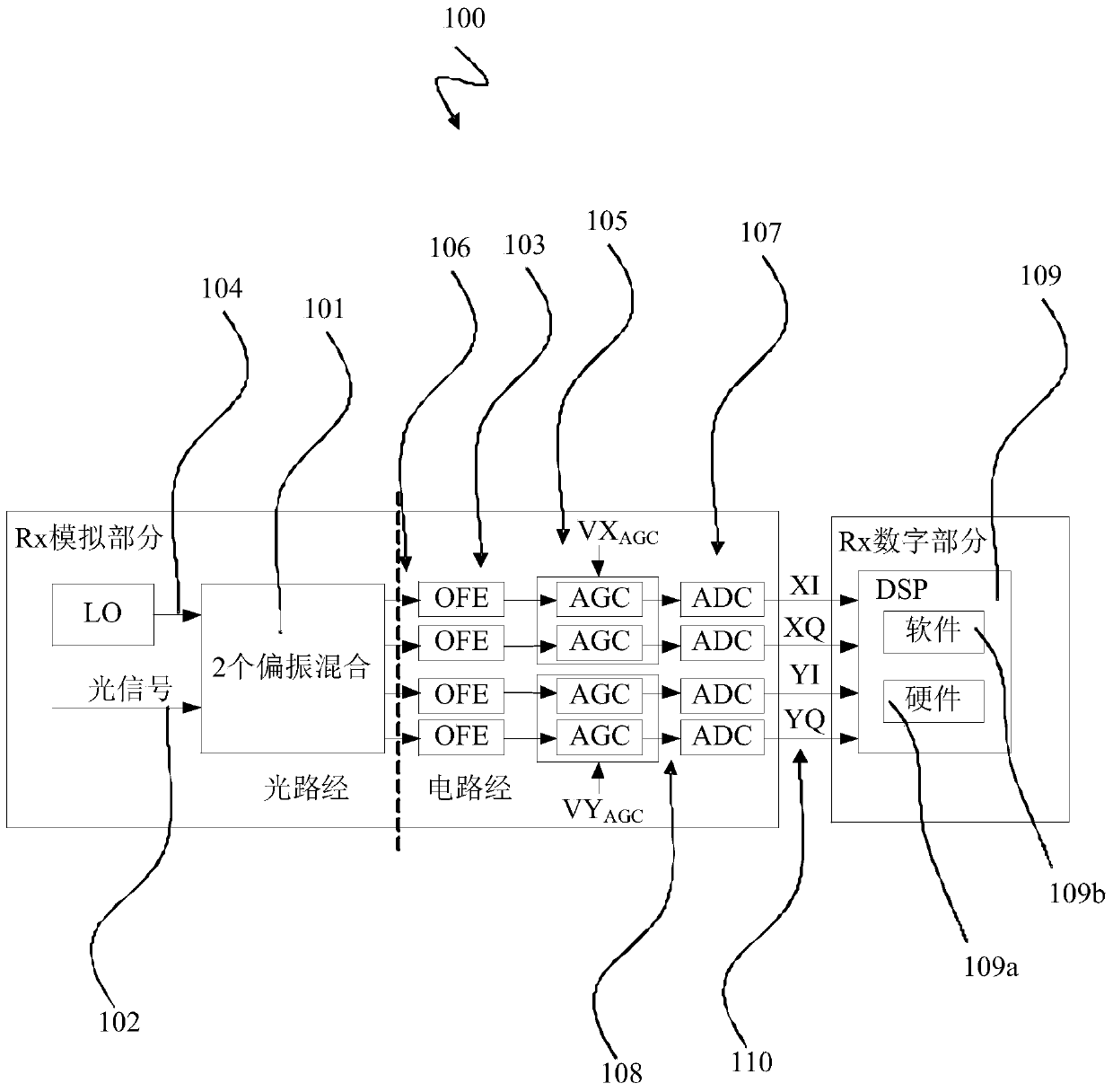
[0112] figure 1 A block diagram illustrating a conventional coherent optical receiver 100 as described above is shown.

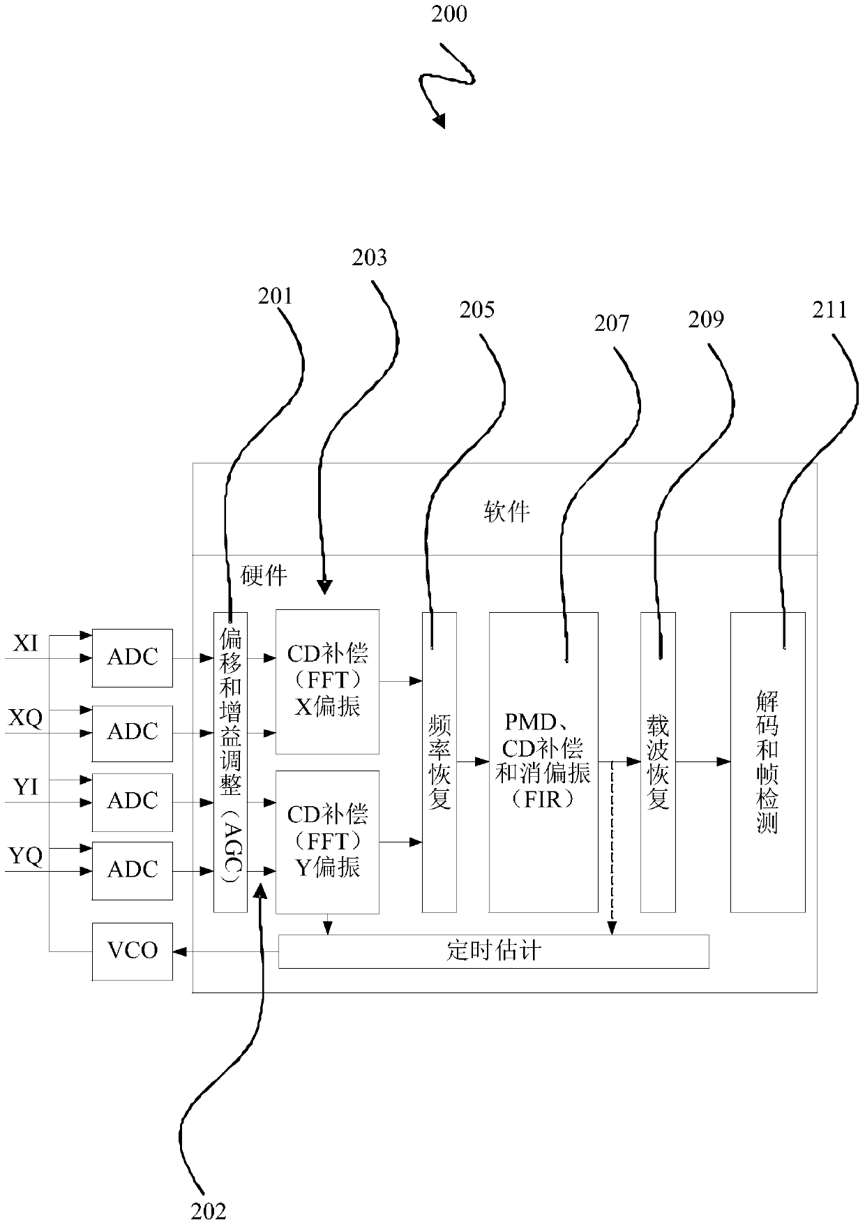
[0113] figure 2 shows instructions as described above figure 1 A block diagram of the basic DSP block 200 of the coherent optical receiver 100 depicted in .

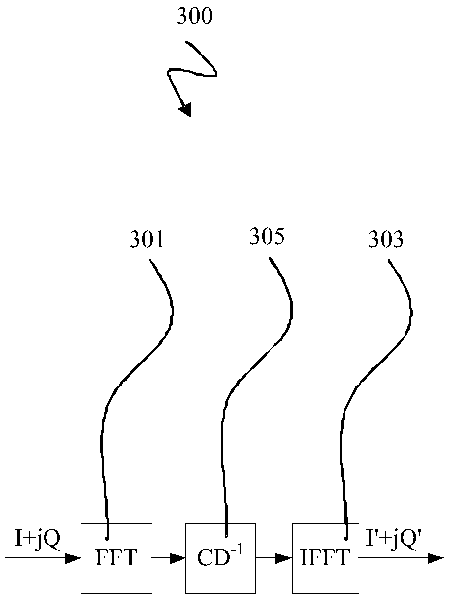
[0114] image 3 shows instructions as described above figure 2 A block diagram of the CD compensation block 300 of the basic DSP block 200 depicted in .

[0115] Figure 4 A graph showing the frequency 400a and impulse response 400b of a conventional raised cosine filter with various roll-off coefficients as described above.

[0116] Figure 5 shows instructions as described above for Figure 4 A diagram of the QPSK Gardner timing error detection characteristics (timing error detection characteristics, TEDC) 500 of the raised cosine filter depicted in 0 to 1 with a roll-off factor of 0.1 in steps.

[0117] Figure 6 shows instructions as described above for Figure 4 The raised cosine filt...


PUM


Abstract

The present invention relates to a coherent optical receiver (800), comprising: an analog-to-digital conversion device (801), configured to sample an analog coherent optical signal (802) into a digital coherent optical signal (804); Channel equalization means (803), for equalizing said digital coherent optical signal (804); channel transfer function calculation means (801), for interpolating said digital coherent optical signal based on interpolation means (807a, 807b) (804) calculating a channel transfer function (808) with said equalized digital coherent optical signal (806), and for adjusting said channel equalization means (803) based on said calculated channel transfer function (808); phase detection means (809), for providing a timing error detection characteristic TEDC signal (810) based on the balanced digital coherent optical signal (806); a feedback timing recovery device (811), for frequency offset compensation criteria based on the TEDC signal (810) adjusting said sampling of said analog-to-digital conversion means (801); and feed-forward timing recovery means (813) for adjusting said interpolation means (807a, 807b) with respect to a phase offset compensation criterion.

Description

technical field [0001] The present invention relates to a coherent optical receiver and a method for clock recovery in a coherent optical receiver. Background technique [0002] An important goal of long-haul fiber optic systems is to transmit the highest data throughput over the longest distances without signal regrowth in opto-electronic optical regenerators. Given the constraints on bandwidth imposed by optical amplifiers and ultimately by the fiber itself, it is important to maximize spectral efficiency. Most current systems use binary modulation formats such as intermittent keying that encodes one bit per symbol. [0003] Advanced modulation formats combined with coherent receivers enable high capacity and spectral efficiency. Polarization multiplexing, quadrature amplitude modulation, and coherent detection are considered a winning combination for next-generation high-capacity optical transmission systems because they allow information encoding with all available deg...

Claims


Application Information

Patent Timeline
Patent Type & Authority Patents(China)
IPC IPC(8): H04L7/00H04B10/61
CPCH04B10/616H04L7/0029H04L7/007H04L7/027H04L7/0335
Inventor 内博伊沙·斯托亚诺维奇
Owner HUAWEI TECH CO LTD
Why Eureka
Try Eureka