
High performance deduster

A high-performance technology for dust collectors, applied in membrane filters, chemical instruments and methods, and dispersed particle filtration, etc., can solve the problems of low dust filtration accuracy, unsuitability for dust or smoke, and poor purification effect of filter bag dust collectors , to achieve the effect of reducing one-time investment cost, overcoming easy wear and tear of the filter cartridge, and avoiding re-adsorption

Pending Publication Date: 2016-03-16
SHENYANG JINWO TECH DEV
View PDF3 Cites 0 Cited by
  • Summary
  • Abstract
  • Description
  • Claims
  • Application Information

AI Technical Summary

Problems solved by technology

[0005] 2. Due to the arrangement of the filter cartridge in the dust-laden gas chamber, the dust adsorbed in the downward folds of the upper filter cartridge flies to the lower part of the filter cartridge under the action of reverse air flow, and falls to the lower filter cartridge under the action of the dust particles’ own weight. Wrinkled upper surface, poor cleaning effect
[0007] 4. Due to the characteristics of the filter cartridge's own structure and the arrangement of the filter cartridge in the dusty gas chamber, the downflow filter cartridge dust collector is only suitable for filtering dust with large or small particle severity
Therefore, the sinking flow filter cartridge dust collector is more suitable for the dust generated in the mechanical casting sand cleaning process or the smoke generated in the tobacco processing process, and the purification effect for other industrial dust dust collection or smoke dust is poor
[0008] The dust filtration accuracy of the filter bag dust collector is low (about 98%), and it is not suitable for filtering dust or smoke with particles below 5 μm
Handling dust content 20g / m 3 The left and right flue gas must be used in series with two bag filter dust collectors to meet the dust emission concentration requirements stipulated by my country's current environmental protection standards. About 99.9%), but the purification effect of filtering industrial dust or smoke other than casting sand cleaning and tobacco treatment is poor, the scope of application is narrow, and the maintenance cost is high

Method used


Image

  • High performance deduster
  • High performance deduster
  • High performance deduster

Examples


Embodiment Construction

[0028] The technical solutions of the present invention will be clearly and completely described below in conjunction with the accompanying drawings of the present invention. Apparently, the described embodiments are only some of the embodiments of the present invention, not all of them. Based on the embodiments of the present invention, all other embodiments obtained by persons of ordinary skill in the art without creative efforts fall within the protection scope of the present invention.

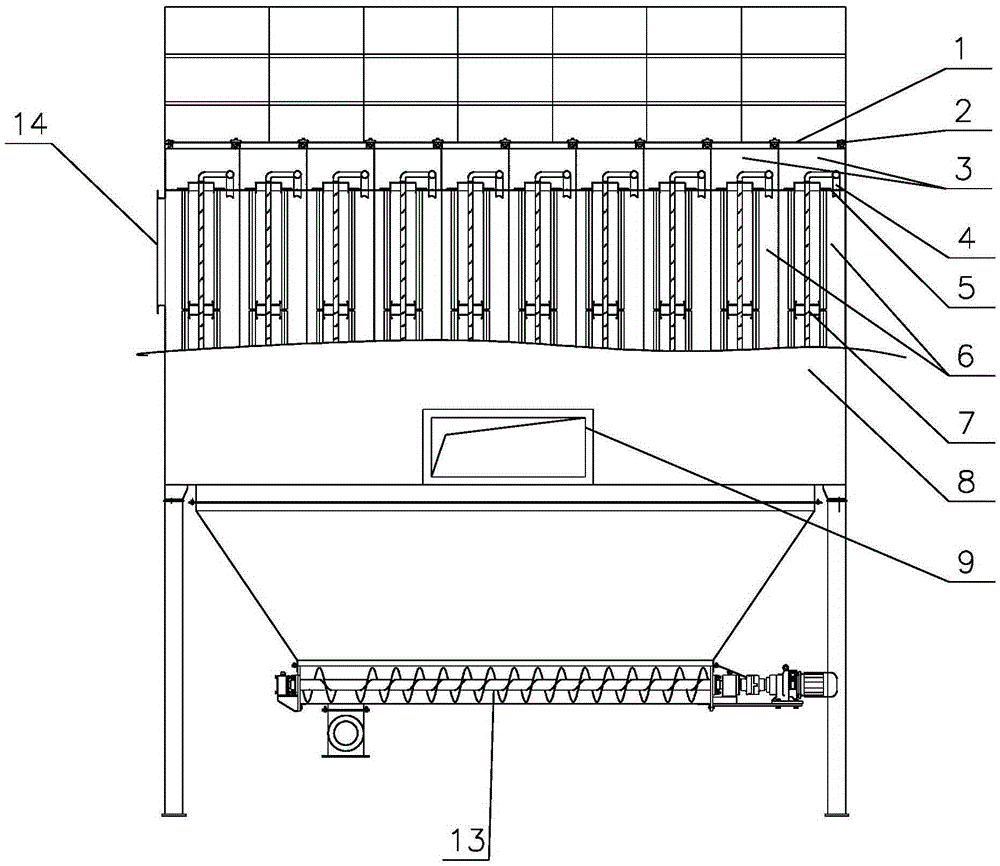
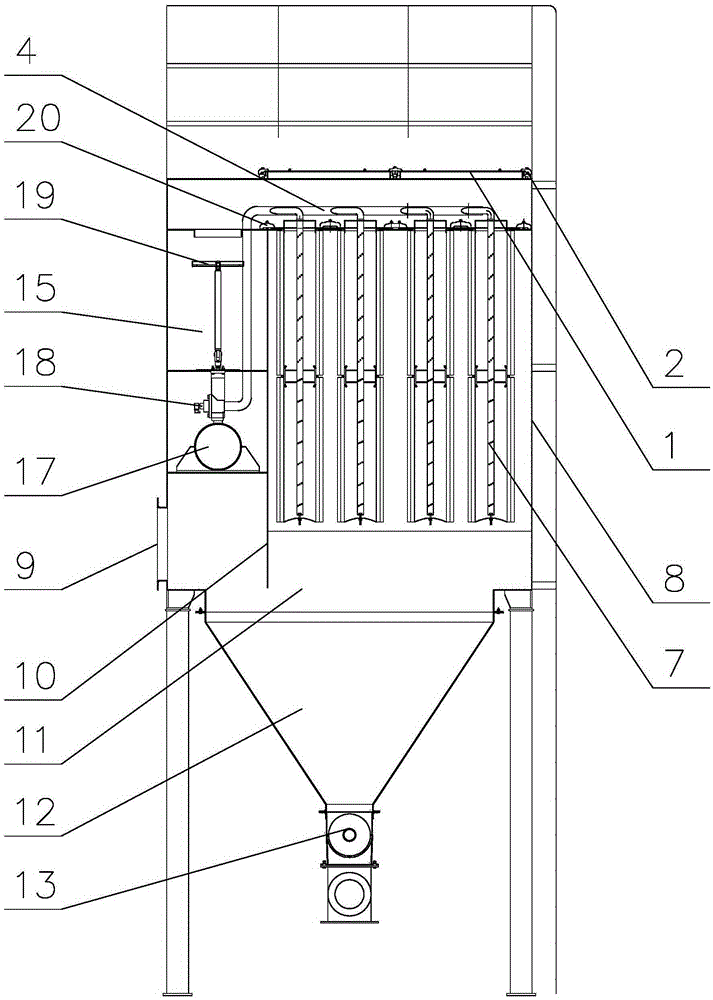
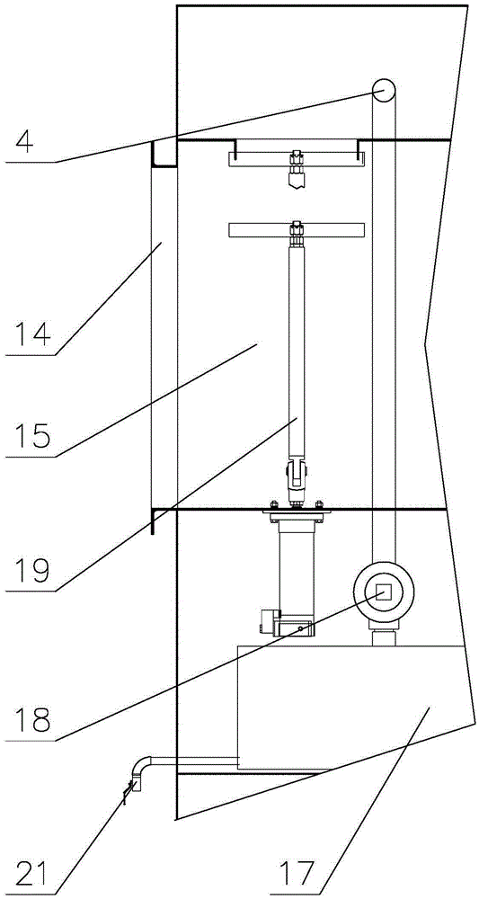
[0029] combine Figure 1-3 As shown, it includes a square upper box body 8 , and the sealing cover 1 and the upper box body 8 are fixedly connected through the sealing cover pressing device 2 . The grate plate 5 located on the upper part of the upper box body 8, the clean gas front chamber 3 located between the grate plate 5 and the upper sealing cover 1, the clean gas rear chamber 15 located at the lower part of the grate plate 5, the dusty gas chamber 6 and Dust gravity settling chamber...


PUM


Abstract

The invention provides a high performance deduster. The high performance deduster comprises an upper box body, the upper box body is provided with a seal cover, a lattice plate is arranged in the upper box body, a cavity between the seal cover and the lattice plate is a clean air cavity, dust-containing air cavities and a dust gravity settlement cavity are sequentially arranged at the lower portion of the clean air cavity, and clean air cavity sealing valves divide the clean air cavity into front clean air cavities and a rear clean air cavity; and a plurality of filter cylinder assemblies are arranged on the lattice plate, and are positioned in the dust-containing air cavity. The high performance deduster has the advantages of high dedusting rate, long service life and low cost.

Description

technical field [0001] The present invention relates to the field of improved filters and filtering methods specially used for separating dispersed particles from gases or vapours, in particular to a high performance dust collector. Background technique [0002] Industrial dust collection and dust purification mainly adopt filter bag filter and downflow filter cartridge filter. The filter bag dust collector uses needle-punched felt as the filter material. Due to the defects in the production of the filter material and the production method of the filter bag, the filtration accuracy of the filter bag is low. The filtration accuracy of the new filter bag is only about 90%. A layer of filter cake (dust layer) is formed on the surface, and the filtration accuracy of the filter bag can reach 99.9% only by the combination of filter material and filter cake. If the thickness of the filter cake is thin, the filtration accuracy cannot be achieved, and if the thickness of the filter ...

Claims


Application Information

Patent Timeline
Patent Type & Authority Applications(China)
IPC IPC(8): B01D50/00B01D46/24B01D46/00
CPCB01D46/2411B01D2267/70B01D2267/30B01D46/62B01D46/71B01D50/20
Inventor 张明凯
Owner SHENYANG JINWO TECH DEV
Learn More