Compound pulse laser drilling method and device

A composite pulse and laser drilling technology, which is used in laser welding equipment, welding equipment, metal processing equipment, etc., can solve the problems of the fan blade not reaching the temperature, shortening the working life of the fan blade, micro-cracks, etc. effect of speed

Active Publication Date: 2017-03-08
AVIC BEIJING AERONAUTICAL MFG TECH RES INST
View PDF5 Cites 0 Cited by
  • Summary
  • Abstract
  • Description
  • Claims
  • Application Information

AI Technical Summary

Problems solved by technology

[0011] To sum up, there are four major problems in the first type of high-energy long-pulse laser drilling: first, there is a recast layer with a thickness of more than 100 microns around the hole wall, and the laser interacts with the spatter and the recast layer. The laser machining small hole has a limit of depth and depth-to-diameter ratio; second, the thermal stress generated by the cooling of the recast layer will produce microcracks on the recast layer and the substrate, and microcracks are the main cause of damage to the turbine blade; First, after the laser is absorbed by the metal, a certain heat-affected zone will be generated; fourth, there will be delamination between the adhesive layer and the thermal barrier coating during the drilling process, so that the fan blade cannot reach the required temperature, and the fan blade will be further shortened. leaf working life
[0012] The second type of short pulse width pulse drilling method can not significantly reduce the thickness of the recast layer when the pulse width is in the range of 50 nanoseconds to 500 nanoseconds. When the pulse width is less than 10 nanoseconds, the drilling efficiency becomes extremely low

Method used


Image

  • Compound pulse laser drilling method and device
  • Compound pulse laser drilling method and device
  • Compound pulse laser drilling method and device

Examples


Embodiment Construction

[0036] The following will clearly and completely describe the technical solutions in the embodiments of the present invention with reference to the accompanying drawings in the embodiments of the present invention. Obviously, the described embodiments are only some, not all, embodiments of the present invention. Based on the embodiments of the present invention, all other embodiments obtained by persons of ordinary skill in the art without making creative efforts belong to the protection scope of the present invention.

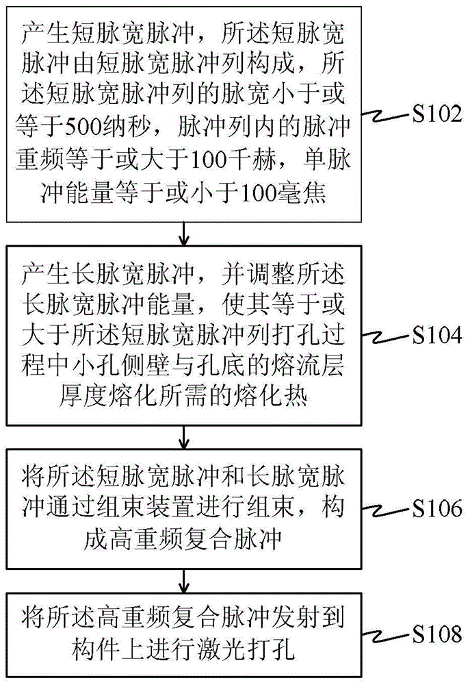
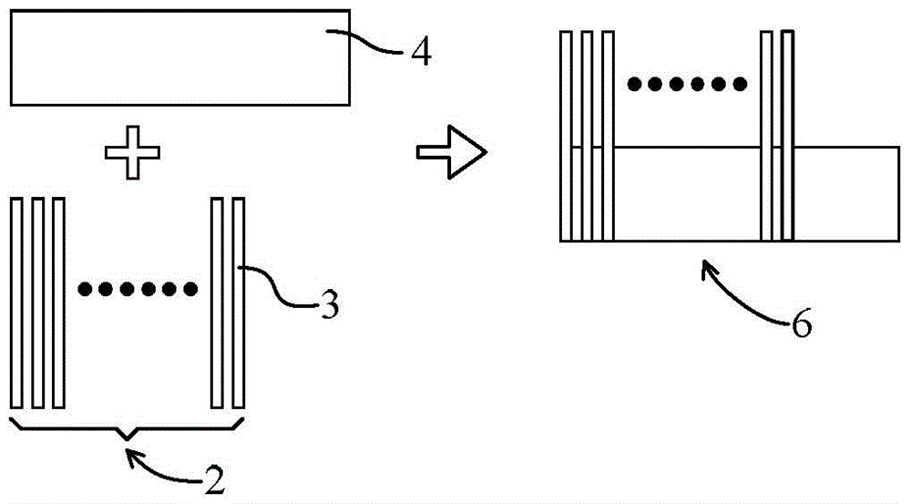
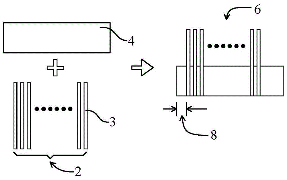
[0037] The principle of the present invention: the nanosecond pulse train processes the small hole melt flow layer is relatively thin, and the microsecond pulse can compensate the melt flow time of the nanosecond pulse and the energy lost on the hole wall, so that the molten residue can be effectively ejected out of the hole outside. That is, the high repetition frequency short pulse width pulse train with nanosecond pulse width is used as the main pulse, and ...


PUM

PropertyMeasurementUnit
wavelengthaaaaaaaaaa

Abstract

The embodiment of the invention provides a composite pulse laser drilling method and device. The composite pulse laser drilling method comprises the following steps: generating a pulse with short pulse width, wherein the pulse with short pulse width comprises a pulse array with short pulse width, and the repetition frequency of the pulses with short pulse width in the pulse array with short pulse width is equal to or larger than 100 kHz; generating a pulse with long pulse width, and adjusting the energy of the pulse with long pulse width to enable the energy to be equal to or larger than melting heat needed in melting of melt-fluid layers of the side wall and the bottom of a small hole during the drilling process of the pulse array with short pulse width; synchronously overlapping the pulse with short pulse width and the pulse with long pulse width through a combining and bunching device, wherein the relative delay time is 0-100 microseconds, and forming a high repetition frequency composite pulse; and transmitting the high repetition frequency composite pulse to a component for laser drilling. The method and the device have the advantages that a film hole can be processed in an aero-engine component with high efficiency and high quality, the thickness of a largest recast layer of the film hole of a blade of a turbine is minimized to 11.5 microns, and the drilling speed of the pulse with short pulse width is about doubled.

Description

technical field [0001] The invention relates to the field of laser drilling, in particular to a compound pulse laser drilling method and device, in particular to a laser drilling method and device for aeroengine components. Background technique [0002] Various known methods for drilling holes in the above-mentioned member, especially using a specific laser device, can be roughly classified into three types according to the pulse width of the laser. [0003] The first type of approach uses flashlamp-pumped millisecond pulsed lasers. This kind of laser generates high-energy long-pulse width pulses with long pulse widths. The pulse width is generally not less than 0.1 milliseconds, such as 1 millisecond; the energy is generally between 1 joule and 300 joules, such as 10 joules. Long-pulse laser drilling produces a large melt flow, and the drilling process, especially the melt flow process after the end of the laser pulse, is difficult to control, resulting in a thicker recast...

Claims


Application Information

Patent Timeline
Patent Type & Authority Patents(China)
IPC IPC(8): B23K26/382B23K26/0622
Inventor 王学军
Owner AVIC BEIJING AERONAUTICAL MFG TECH RES INST
Why Eureka
Try Eureka