CAN bus fault monitoring and displaying system for vehicle-mounted controller

A vehicle-mounted controller and display system technology, which is applied to vehicle components, circuits or fluid pipelines, transportation and packaging, etc., to achieve the effect of avoiding vehicle and personal safety problems

Inactive Publication Date: 2016-03-16
BRILLIANCE AUTO
View PDF4 Cites 5 Cited by
  • Summary
  • Abstract
  • Description
  • Claims
  • Application Information

AI Technical Summary

Problems solved by technology

In order to solve the problem of the safety of the automobile CAN bus, realize the real-time monitoring of the CAN bus of the automobile on-board controller

Method used


Image

  • CAN bus fault monitoring and displaying system for vehicle-mounted controller
  • CAN bus fault monitoring and displaying system for vehicle-mounted controller

Examples


example 1

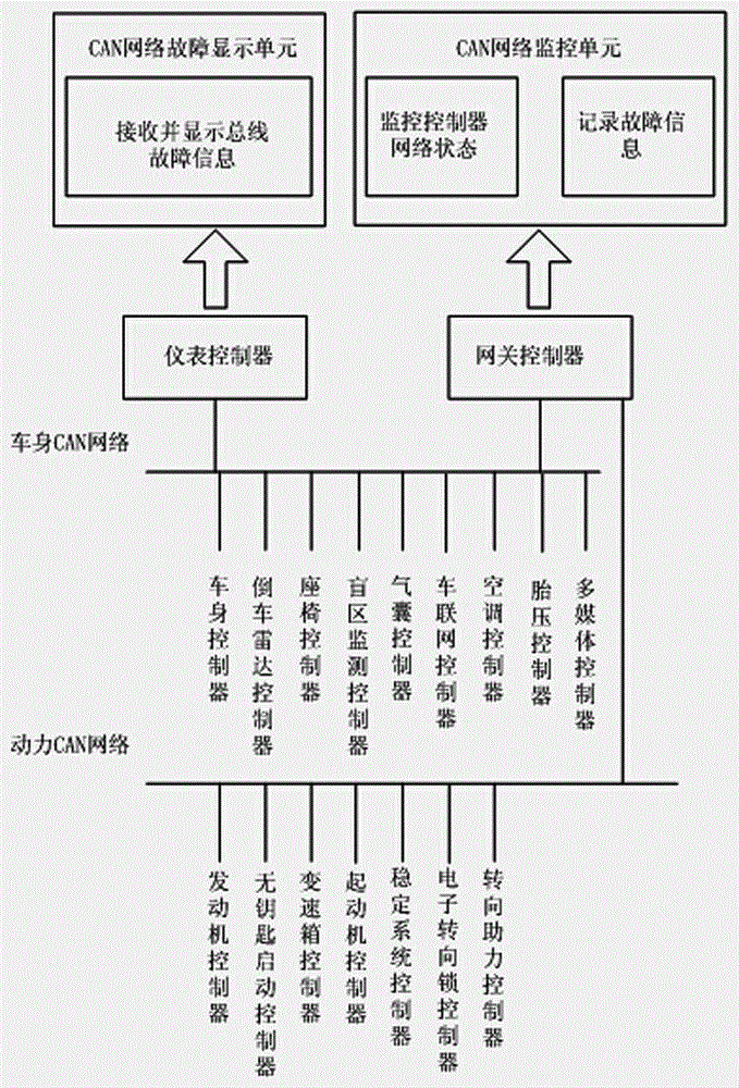
[0029] Depend on Figure 1-2 As shown, this example is designed for the network architecture of high-end vehicles. figure 1 It is a block diagram of the working principle of the vehicle controller CAN bus fault monitoring and display system, which includes an engine controller, a gearbox controller, an electronic steering lock controller, a power steering controller, a starter controller, a stability system controller and Power CAN network with keyless start controller, as well as body controller, airbag controller, air conditioning controller, multimedia controller, reversing radar controller, blind spot monitoring controller, seat controller, car networking controller and tire Body CAN network for pressure controllers. The output end of the described power CAN network and the vehicle body CAN network is connected with the gateway controller, and the output end of the gateway controller is connected with the input end of the CAN network monitoring unit with monitoring contro...

example 2

[0033] This example is designed for the network architecture of low-end vehicles. In the network architecture of low-end vehicles, it mainly includes the following on-board controllers and body CAN networks: body controllers, airbag controllers, multimedia controllers, and instrument control. The device is connected with the input end of the CAN network fault display unit capable of receiving and displaying bus fault information. Power CAN network: engine controller, gearbox controller, power steering controller, electronic steering lock controller. The gateway is respectively connected to the body CAN network and the power CAN network, and is responsible for signal routing.

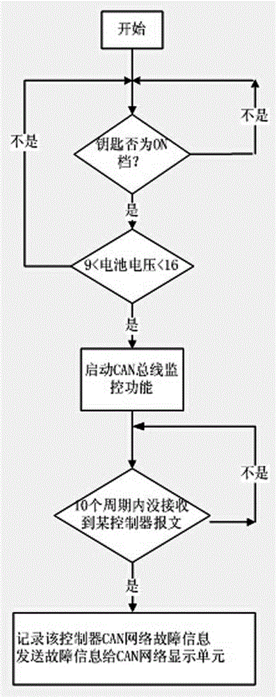
[0034] Same as the high-end vehicle example, the gateway is used as the CAN network monitoring unit of the vehicle controller CAN bus fault monitoring and display system to monitor the CAN network faults of all vehicle controllers on the bus. The information is passed to the instrument controller. As t...


PUM


Abstract

A CAN bus fault monitoring and displaying system for a vehicle-mounted controller comprises a power CAN network and a vehicle body CAN network, wherein the power CAN network is provided with an engine controller, a gearbox controller, an electronic steering lock controller and a steering power-assisted controller; and the vehicle body CAN network is provided with a vehicle body controller, an airbag controller, an air conditioner controller and a multimedia controller. The CAN bus fault monitoring and displaying system for the vehicle-mounted controller is characterized in that output ends of the power CAN network and the vehicle body CAN network are connected with a gateway controller; an output end of the gateway controller is connected with an input end of a CAN network monitoring unit for monitoring controller network state and recording fault information; and through an instrument controller, the output end of the vehicle body CAN network is connected with an input end of a CAN network fault displaying unit capable of receiving and displaying bus fault information. According to the invention, as the instrument controller is used as the CAN network fault displaying unit, a driver can know automobile controller network fault states in time so as to adopt corresponding measures so that vehicle and personal safety problems are avoided.

Description

technical field [0001] The invention is mainly used in the field of automotive electronic fault detection, specifically a vehicle controller CAN network monitoring and display system for monitoring and displaying the CAN bus network status of the vehicle controller. Background technique [0002] As modern cars become more and more intelligent and their functions more and more complex, there are more and more information interactions between on-board controllers on the CAN bus. Many functions require several controllers to cooperate together. If the controller CAN bus fails, it will cause functional problems of other controllers, and even threaten the safety of the vehicle and driver in many cases. Therefore, how to design a vehicle controller CAN bus fault monitoring and display system, when the vehicle controller CAN bus fails, to detect the fault in time and remind the driver has always been a very important issue. Contents of the invention [0003] The purpose of the p...

Claims


Application Information

Patent Timeline
Patent Type & Authority Applications(China)
IPC IPC(8): B60R16/023
CPCB60R16/0232
Inventor 王志鹏赵德华张超詹德凯
Owner BRILLIANCE AUTO
Why Eureka
Try Eureka