
Welded pipe drying device

A drying device and welded pipe technology, applied in the direction of drying gas arrangement, drying, dryer, etc., can solve the problems of air pollution and low drying efficiency, and achieve good results

Inactive Publication Date: 2016-03-16
CHONGQING GUANGJI IND
View PDF0 Cites 1 Cited by
  • Summary
  • Abstract
  • Description
  • Claims
  • Application Information

AI Technical Summary

Problems solved by technology

However, the drying method in the prior art has low drying efficiency and also produces air pollution.

Method used


Image

  • Welded pipe drying device
  • Welded pipe drying device

Examples


Embodiment Construction

[0017] Below in conjunction with accompanying drawing, the present invention will be further described.

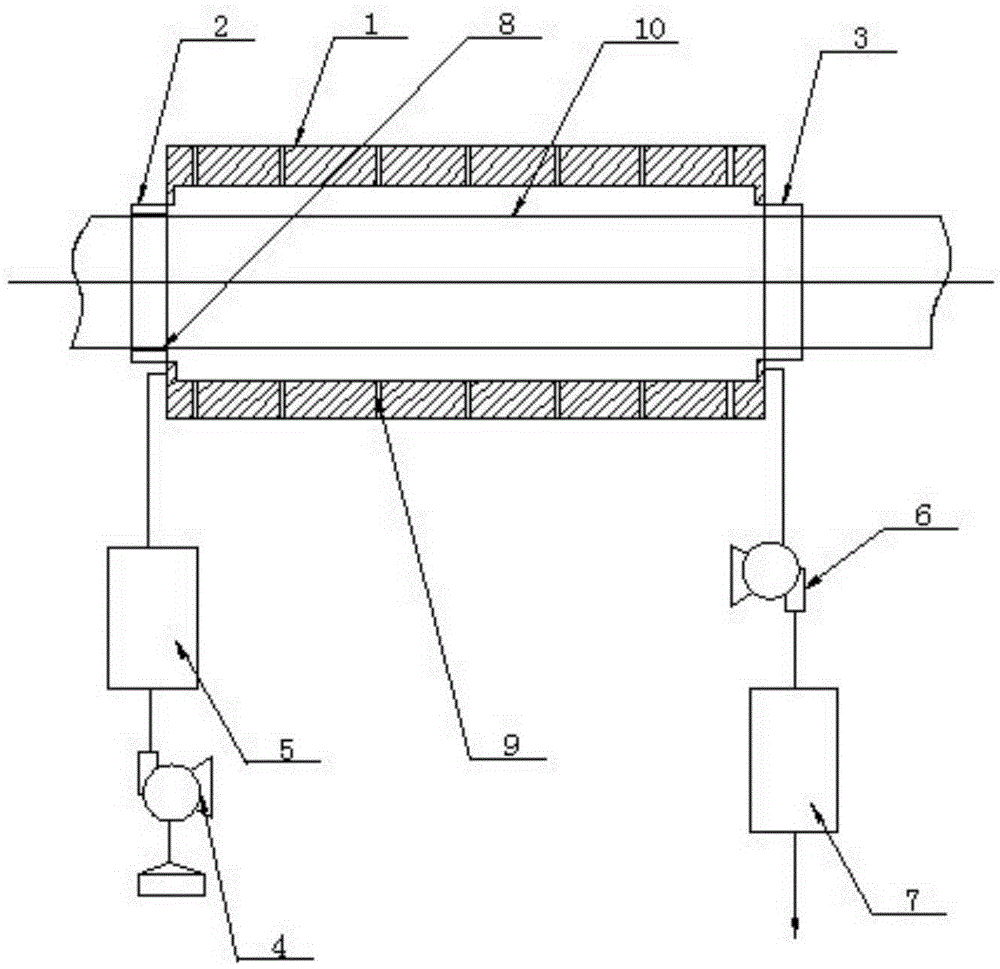
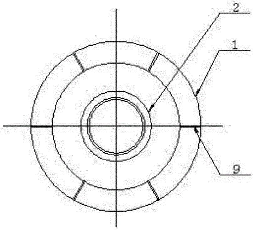
[0018] see as figure 1 —— figure 2 As shown, this specific embodiment adopts the following technical scheme: it includes an annular air chamber 1, a left support joint 2, a right support joint 3, a blower 4, an air heater 5, an induced draft fan 6, an apron 8, and a through hole 9; One end of the annular air cavity 1 is fixedly connected with a left support joint 2, and the other end of the annular air cavity 1 is fixedly connected with a right support joint 3; the air blower 4 is connected with the air heater 5, and the air heater 5 is connected with the annular air One end of the chamber 1 is connected; the other end of the annular air chamber 1 is connected with an induced draft fan 6; the inner wall of the left supporting joint 2 is provided with an apron 8, and the inner wall of the annular air chamber 1 is provided with an inner chamber communicating with the outsi...


PUM


Abstract

The invention discloses a welded pipe drying device and relates to the technical field of welded pipe drying. The welded pipe drying device comprises an annular air cavity, a left supporting connector, a right supporting connector, an air feeder, an air heater, an inducing fan, a rubber ring and through holes. One end of the annular air cavity is fixedly connected with the left supporting connector, and the other end of the annular air cavity is fixedly connected with the right supporting connector. The air feeder is connected with the air heater. The air heater is connected with one end of the annular air cavity. The other end of the annular air cavity is connected with the inducing fan. The rubber ring is arranged on the inner wall of the left supporting connector. The annular air cavity is provided with the through holes communicating an inner cavity of the annular air cavity with the outside. The welded pipe drying device is high in drying efficiency and capable of purifying air after welded pipe drying, and has the advantages of being simple in structure, reasonable in design, low in manufacturing cost and the like.

Description

technical field [0001] The invention relates to the technical field of welded pipe drying, in particular to a welded pipe drying device. Background technique [0002] Welded steel pipe, also known as welded pipe, is a steel pipe made of steel plate or strip steel after crimping and welding, generally with a length of 6 meters. The production process of welded steel pipe is simple, the production efficiency is high, there are many varieties and specifications, and the investment in equipment is small, but the general strength is lower than that of seamless steel pipe. [0003] With the rapid development of continuous rolling production of high-quality strip steel and the advancement of welding and inspection technology, the quality of welds has been continuously improved, and the varieties and specifications of welded steel pipes have increased day by day, and seamless steel pipes have been replaced in more and more fields. Welded steel pipes are divided into straight seam w...

Claims


Application Information

Patent Timeline
Patent Type & Authority Applications(China)
IPC IPC(8): F26B21/00
Inventor 焦长暮春
Owner CHONGQING GUANGJI IND
Learn More