
Textile drying box

A textile and oven technology, applied in the textile field, can solve the problems of slow heating time, burns of staff, insufficient drying effect, etc., achieve good drying effect and avoid direct contact

Pending Publication Date: 2017-10-24
朱新超
View PDF5 Cites 2 Cited by
  • Summary
  • Abstract
  • Description
  • Claims
  • Application Information

AI Technical Summary

Problems solved by technology

However, the existing textile ovens are all equipped with a heating device in the shell, and then heat the inside through the air duct. This heating method will heat the shell at the same time, so that the heat will be lost. First, it will cause waste of resources. There is a possibility of scalding the staff
And this heating method must be preheated for a period of time, so that the inside of the textile oven reaches a certain temperature before the fabric can be heated, and heat exchange is performed through the air. The heating time is relatively slow, but the existing textile oven consumes a lot of energy, and drying Insufficient effect, the textile oven is one of the indispensable production equipment in the textile production process, the quality of the textile oven will directly affect the quality of the textile, the existing textile oven mainly includes a drying box and a drying box set on the drying box heating device
However, the high temperature of the existing heating device can easily damage the textiles, resulting in poor drying effect

Method used


Image

  • Textile drying box
  • Textile drying box
  • Textile drying box

Examples


Embodiment 1

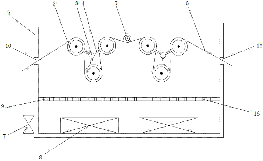
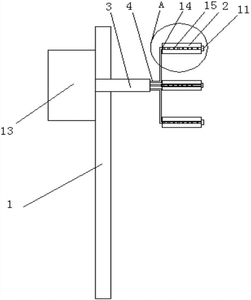
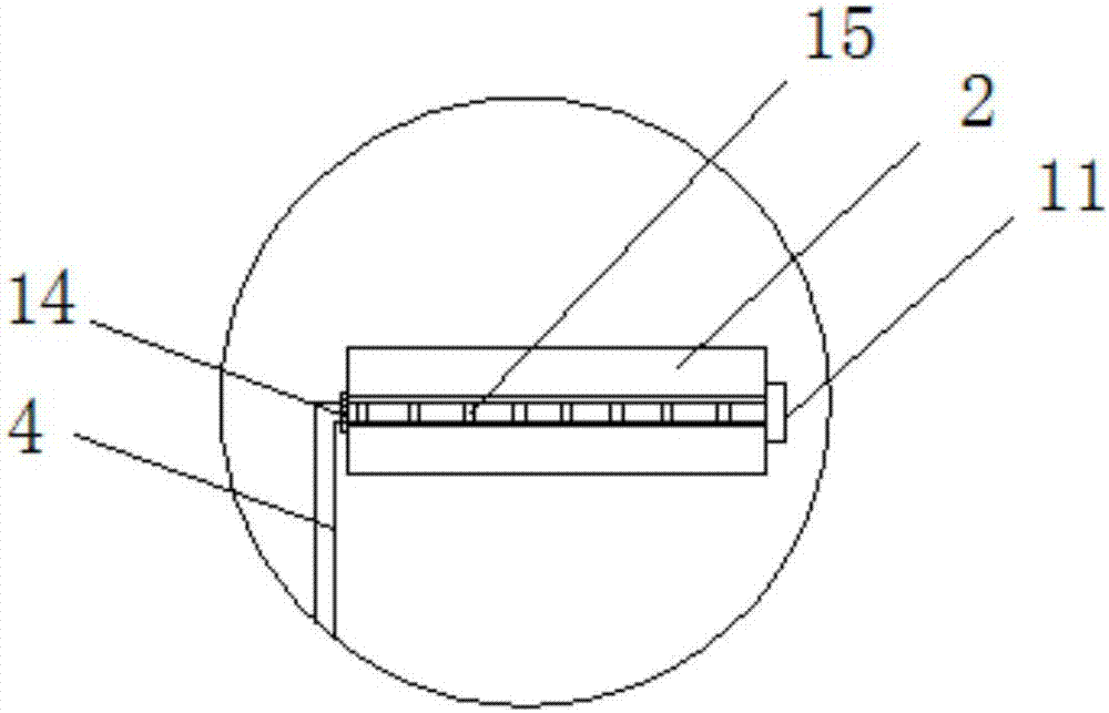
[0030] see Figure 1-3 , a textile oven, comprising a textile drying box 1, one end of the side wall of the textile drying box 1 is provided with a drying inlet 12, and the other end is provided with a drying outlet 10, and the bottom of the textile drying box 1 is connected with Two hot air blowers 8, a hot air blower controller 7 is fixedly connected to the textile drying box 1 below the drying outlet 10, and the hot air blower controller 7 is connected to the hot air blower 8, above the hot air blower 8, and is located in the textile drying The inner wall of the box body 1 is fixedly connected with a windshield 9, and the windshield 9 is provided with a ventilation hole 16, above the windshield 9, and is located on the textile drying box 1, and is fixedly connected with two textile drying The roller group, the textile drying box 1 between the two textile drying roller groups is fixedly connected with the supporting textile drying roller shaft 5, and each textile drying roll...


PUM


Abstract

The invention discloses a textile drying box and belongs to the textile field. The textile drying box comprises a textile drying box body. A drying inlet is formed in one end of the side wall of the textile drying box body, and a drying outlet is formed in the other end of the side wall of the textile drying box body. Two air heaters are connected to the bottom inside the textile drying box body. Two textile drying roller shaft sets are fixedly connected to the textile drying box body. Each textile drying roller shaft set comprises three textile drying roller shafts. A textile is placed on the textile drying roller shafts. The textile drying roller shafts are arranged on supporting pipes in a sleeving mode. The supporting pipes are fixedly connected to steam pipelines. The steam pipelines penetrate through the textile drying box body and are fixedly connected to a steam generator. According to the textile drying box, high-temperature steam in the supporting pipes can be introduced, penetrates through the steam pipelines and heats the textile drying roller shafts, and the pre-drying effect on the textile on the textile drying roller shafts is achieved; hot air blown out by the air heaters penetrates through ventilation holes and further dries the textile on the textile drying roller shafts; and the two sets of textile drying roller shafts are adopted and triangularly arranged in the space, direct contact between a heating device and the textile is avoided, and the drying effect is good.

Description

technical field [0001] The invention relates to the field of textiles, more specifically, to a textile oven. Background technique [0002] As we all know, the textile oven is one of the indispensable production equipment in the production of textiles. The quality of the textile oven will directly affect the quality of the textile. The existing textile oven mainly includes a drying box and a The heating device, the heating device heats up to make the temperature in the drying box meet the specification requirements, and then dries the cloth in the drying box. However, the existing textile ovens are all equipped with a heating device in the shell, and then heat the inside through the air duct. This heating method will heat the shell at the same time, so that the heat will be lost. First, it will cause waste of resources. It is possible to burn the staff. And this heating method must be preheated for a period of time, so that the inside of the textile oven reaches a certain t...

Claims


Application Information

Patent Timeline
Patent Type & Authority Applications(China)
IPC IPC(8): F26B13/18F26B21/00
CPCF26B13/183F26B21/004F26B21/005
Inventor 朱新超
Owner 朱新超
Learn More