

Automatic zero drift-correction ultrasound water meter and correction method
A zero-point drift, automatic correction technology, applied in testing/calibration devices, measuring devices, instruments, etc., can solve problems such as exceeding the range of the maximum allowable error and changing the indication error of the small flow measurement section, and achieve the effect of maintaining accuracy
- Summary
- Abstract
- Description
- Claims
- Application Information
AI Technical Summary
Problems solved by technology
Method used
Image

Examples
Embodiment 1
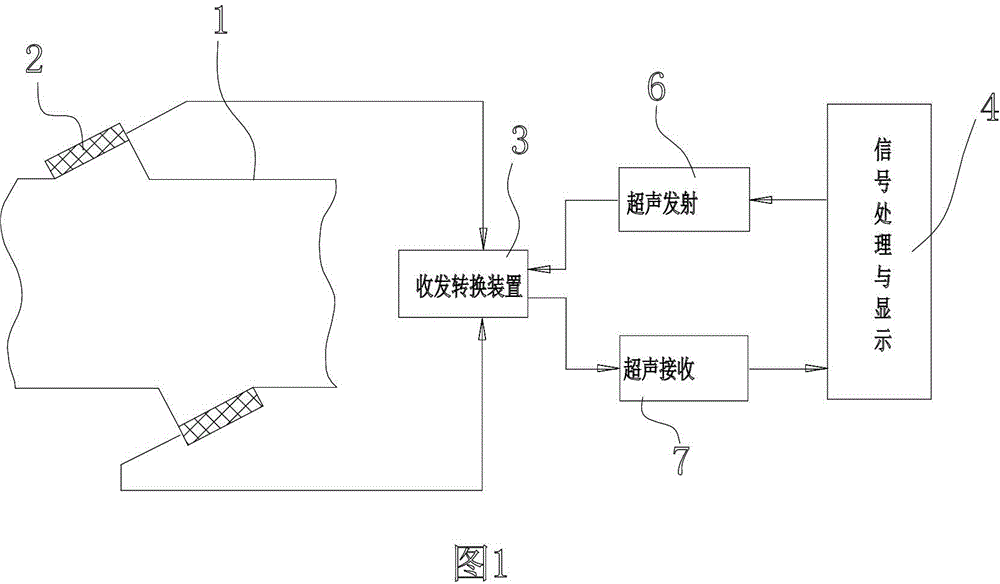
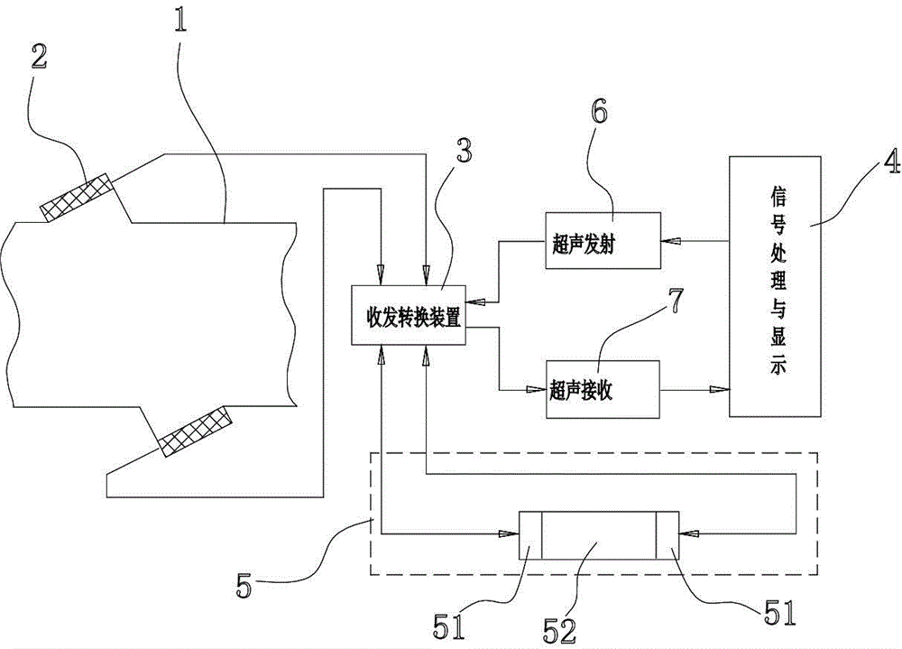
[0025] Embodiment 1: see figure 2 and image 3 , an ultrasonic water meter that automatically corrects zero point drift, including a measuring tube 1, a group of measuring transducers 2 are correspondingly arranged on the measuring tube 1, and the measuring transducers 2 are connected with a signal transceiving conversion device 3 , the signal transceiving conversion device 3 is connected with a signal processing and display device 4, specifically to this embodiment, the signal transceiving conversion device 3 and the signal processing and display device 4 are connected by an ultrasonic transmitting device 6 and an ultrasonic receiving device 7 Realize the signal transmission. The ultrasonic water meter also includes a zero-flow auxiliary correction transducer group 5, which is used to detect the ultrasonic propagation time difference of the transducer under no flow interference, which is connected with the signal transceiver conversion device 3 Phase signal connection and ...
Embodiment 2
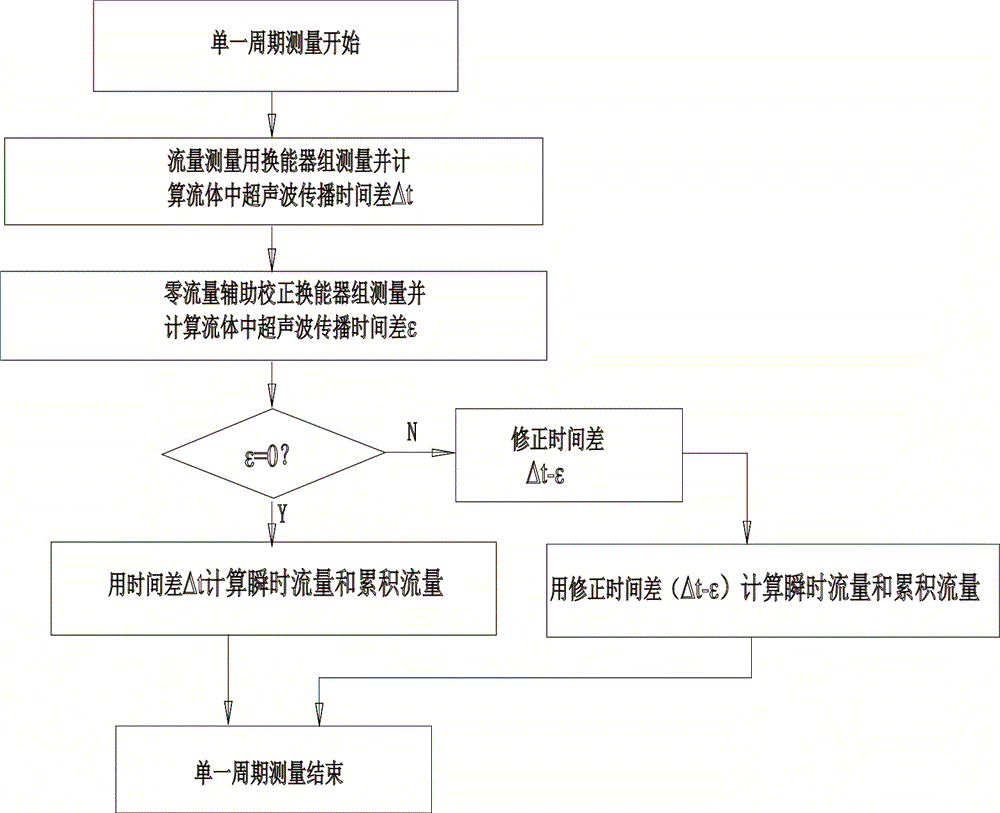
[0028] Example 2: Participation Figure 4 , the present embodiment adopts the same ultrasonic water meter as in Embodiment 1, and adopts the following method during calibration: a method for calibrating the zero drift of the ultrasonic water meter, which is characterized in that it comprises the following steps: a. And calculate the difference in ultrasonic propagation time in the fluid ; b, the zero-flow auxiliary correction transducer group 5 simultaneously measures the ultrasonic propagation time difference of the transducer under no flow interference c, the results measured in step a and step b are all transmitted to the signal processing and display device 4 through the signal transceiving conversion device 3; d, the signal processing and display device 4 correct the time difference as - , then use - Calculate instantaneous flow and cumulative flow.
PUM
 Abstract
Description
Claims
Application Information