
Response time calibration device of temperature sensor

A temperature sensor and response time technology, applied in the field of temperature sensor response time calibration, can solve the problems of low response time accuracy, unreliable response time, low calibration accuracy, etc., achieve reliable response time, ingenious design, and improve calibration The effect of precision

Inactive Publication Date: 2016-03-16
ZHONGBEI UNIV
View PDF5 Cites 7 Cited by
  • Summary
  • Abstract
  • Description
  • Claims
  • Application Information

AI Technical Summary

Problems solved by technology

[0003] In order to solve the problems of low calibration accuracy, inability to obtain reliable response time, and low accuracy of response time obtained in the flame temperature field environment in the existing temperature sensor response time calibration method, the present invention provides A Response Time Calibration Device for Temperature Sensors

Method used


Image

  • Response time calibration device of temperature sensor
  • Response time calibration device of temperature sensor

Examples


Embodiment 1

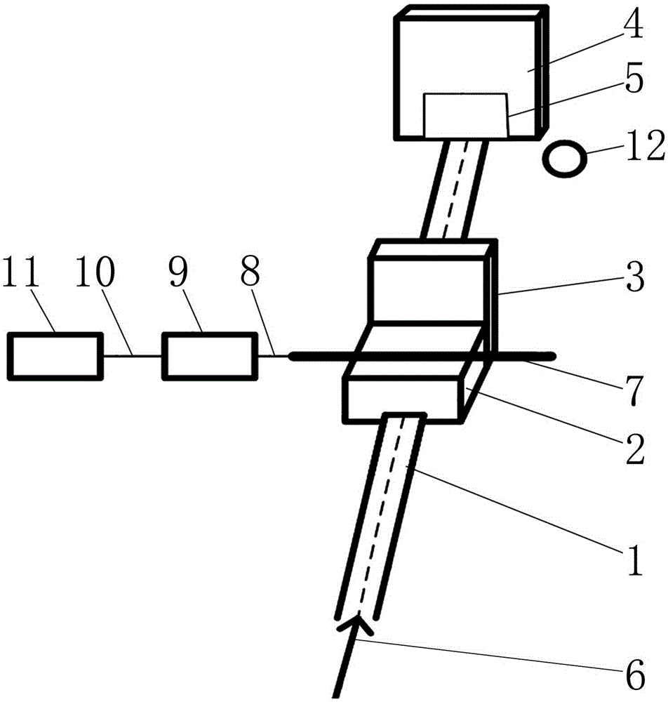
[0021] A response time calibration device for a temperature sensor, comprising a longitudinal linear guide rail 1, a slider with pulleys 2, a small vertical baffle 3, a large vertical baffle 4, a quick adsorption piece 5, a quick ejection device 6, and a temperature sensor 7 , compensation wire 8, signal acquisition and processing integrated circuit 9, data transmission line 10, data display device 11, flame temperature source 12;

[0022] Wherein, the slider 2 with a pulley is slidably installed on the longitudinal linear guide rail 1;

[0023] The lower part of the rear surface of the vertical small baffle plate 3 is fixed to the front surface of the slide block 2 with pulleys;

[0024] The middle part of the lower surface of the vertical large baffle 4 is fixed to the front part of the upper surface of the longitudinal linear guide rail 1, and the rear surface of the vertical large baffle 4 is parallel to the front surface of the vertical small baffle 3;

[0025] The numbe...

Embodiment 2

[0034] A response time calibration device for a temperature sensor, comprising a longitudinal linear guide rail 1, a slider with pulleys 2, a small vertical baffle 3, a large vertical baffle 4, a quick adsorption piece 5, a quick ejection device 6, and a temperature sensor 7 , compensation wire 8, signal acquisition and processing integrated circuit 9, data transmission line 10, data display device 11, flame temperature source 12;

[0035] Wherein, the slider 2 with a pulley is slidably installed on the longitudinal linear guide rail 1;

[0036]The lower part of the rear surface of the vertical small baffle plate 3 is fixed to the front surface of the slide block 2 with pulleys;

[0037] The middle part of the lower surface of the vertical large baffle 4 is fixed to the front part of the upper surface of the longitudinal linear guide rail 1, and the rear surface of the vertical large baffle 4 is parallel to the front surface of the vertical small baffle 3;

[0038] The number...


PUM


Abstract

The invention relates to a response time calibration technology of a temperature sensor, and specifically relates to a response time calibration device of a temperature sensor. The response time calibration device of the temperature sensor solves the problems that calibration precision is low when an existing response time calibration method of a temperature sensor calibrates a small-response-time temperature sensor, reliable response time cannot be obtained, and accuracy of response time obtained in a flame temperature field environment is low. The response time calibration device of the temperature sensor comprises a longitudinal linear guide rail, a slide block with a pulley, a vertical small baffle plate, a vertical big baffle plate, a rapid adsorption sheet, a rapid ejection device, a temperature sensor, a compensation lead, a signal acquisition and processing integration circuit, a data transmission line, a data display device and a flame temperature source. The response time calibration device is suitable for performing response time calibrations of the temperature sensor in various environments, and is especially suitable for performing the response time calibration of the temperature sensor in the flame temperature field environment.

Description

technical field [0001] The invention relates to a response time calibration technology of a temperature sensor, in particular to a response time calibration device of a temperature sensor. Background technique [0002] In the transient temperature measurement under special environment (such as high temperature, high pressure, strong ionization environment), the temperature sensor used is required to have the characteristics of good dynamic response characteristics, small heat capacity and almost no interference to the test environment. Among them, the dynamic response characteristics of the temperature sensor have received much attention, and the response time of the temperature sensor is the main index reflecting its dynamic response characteristics. Therefore, in order to measure the transient temperature accurately, it is necessary to calibrate the response time of the temperature sensor used. Under the existing technical conditions, the response time calibration methods...

Claims


Application Information

Patent Timeline
Patent Type & Authority Applications(China)
IPC IPC(8): G01K15/00
CPCG01K15/007
Inventor 王文廉赵学敏李岩峰赵晨阳
Owner ZHONGBEI UNIV
Learn More