Low voltage three-phase load balancing control method based on on-load commutation technology

A technology of load balancing and control method, applied in the field of control, can solve the problems of difficult three-phase load balancing, short service life, high cost, etc., and achieve economical and efficient three-phase load balancing, fewer switching operations, and low commutation costs. Effect

Active Publication Date: 2016-03-16
STATE GRID CORP OF CHINA +3
View PDF5 Cites 20 Cited by
  • Summary
  • Abstract
  • Description
  • Claims
  • Application Information

AI Technical Summary

Problems solved by technology

Three-phase unbalance will lead to additional heating and vibration of rotating motors, increased magnetic flux leakage and local overheating of transformers, increased power grid line losses, and misoperation of various protection and automatic devices, etc.
[0005] However, the reactive power adjustment and compensation devices developed by related manufacturers, due to the complex and changeable operating conditions of inductive loads in the low-voltage distribution network, make it difficult to achieve the desired effect with relatively fixed capacitor compensation, and often cause problems in the reactive power transfer system. The effect of energy saving and loss reduction is not obvious
On the other hand, the TCR branch in the traditional SVC adopts the 6-pulse connection form, and its line current contains 6k±1 order harmonics (k is a positive integer), so it is necessary to install a filter device, which increases the cost
If the current advanced STATCOM technology is adopted, the cost is too high, and it is unreasonable to adopt it in the low-voltage system
In the third aspect, the adjustment and compensation

Method used


Image

  • Low voltage three-phase load balancing control method based on on-load commutation technology
  • Low voltage three-phase load balancing control method based on on-load commutation technology
  • Low voltage three-phase load balancing control method based on on-load commutation technology

Examples


Embodiment Construction

[0031] In order to make the technical means, creative features, goals and effects achieved by the present invention easy to understand, the present invention will be further described below in conjunction with specific embodiments.

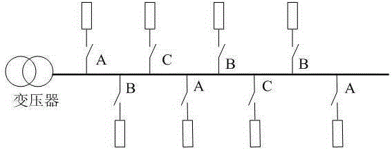
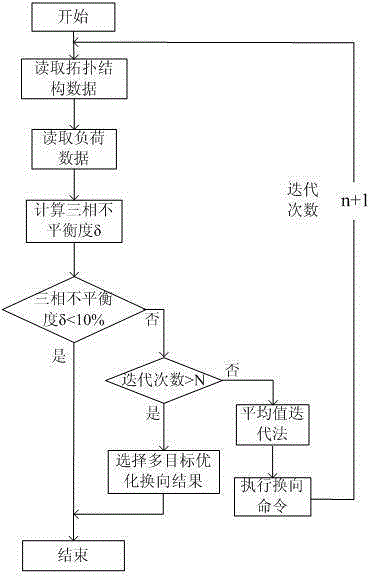
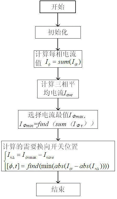
[0032] see Figure 1-Figure 3 , a low-voltage three-item load balance control method based on on-load reversing technology in this embodiment, using each outgoing line on the low-voltage side of the distribution transformer as a model, collecting the load controlled by the reversing switch and the switch position on each outgoing line, Real-time detection and calculation of three-phase load unbalance, if the three-phase unbalance exceeds a given value, the load that needs to be adjusted is calculated through the mean value iterative method, and then the reversing switch number and reversing switch that need to be operated are obtained based on the principle of multi-objective optimization. Phase sequence adjusted by the switch to achieve three-pha...


PUM


Abstract

The invention discloses a low voltage three-phase load balancing control method based on the on-load commutation technology. According to the method, each outgoing topology structure at a low voltage side of a distribution transformer on an outgoing wire is taken as a model, a control load capacity and a switch position of a commutation switch on the outgoing wire are acquired, a three-phase load unbalancing degree is detected and calculated in real time, if the three-phase load unbalancing degree surpasses a given value, an adjustment-needing load is calculated through a mean value iterative method, a motion-needing commutation switch number and a commutation switch adjustment phase sequence are acquired through utilizing the multi-target optimization principle, and three-phase load balancing is realized. According to the method, factors such as the switch motion frequency and the three-phase load unbalancing degree are fully considered, when the three-phase load unbalancing degree is guaranteed to reach a standard value scope, the smallest switch motion frequency and the lowest commutation cost are realized, moreover, uninterrupted user power supply requirements are realized during load transfer, namely the on-load commutation technology.

Description

technical field [0001] The invention mainly relates to the three-phase load balance control of the low-voltage line of the distribution network. Based on the theory of the three-phase load balance algorithm, the load-on-load commutation is realized, and belongs to the field of control technology. Background technique [0002] In the three-phase four-wire system of urban residents and rural low-voltage distribution networks, most users use single-phase loads or single-phase and three-phase loads. Due to unbalanced loads and asymmetrical system component parameters, the unbalanced current between the three phases is objective ubiquitous. At the same time, the irregularity and unpredictability of user load imbalance lead to long-term imbalance of three-phase load in low-voltage distribution network. GB / T15543-2008 "Permissible Unbalance of Three-phase Voltage of Power Quality" clearly stipulates that under normal circumstances, the three-phase unbalance of negative sequence vo...

Claims


Application Information

Patent Timeline
IPC IPC(8): H02J3/26
CPCY02E40/50
Inventor 周建华陈久林孙蓉石文娟向驰左高周学俊于伟
Owner STATE GRID CORP OF CHINA
Why Eureka
Try Eureka