Electrical Machine With Armature

A technology of armature and armature shaft, which is applied in the manufacture of motor generators, electrical components, electromechanical devices, etc., to achieve the effect of flexible process design and saving parts

Active Publication Date: 2016-03-16
ROBERT BOSCH GMBH
View PDF7 Cites 4 Cited by
  • Summary
  • Abstract
  • Description
  • Claims
  • Application Information

AI Technical Summary

Problems solved by technology

This results in parts savings

Method used


Image

  • Electrical Machine With Armature

Examples


Embodiment Construction

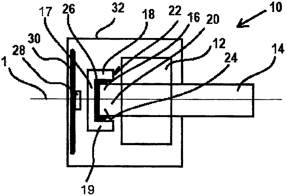
[0017] figure 1 The motor 10 is shown in . The electric machine 10 has a housing 32 . The armature 12 is arranged within the housing 32 . An armature shaft 14 is arranged along the axis of rotation 1 of the armature 12 . The armature shaft 14 protrudes from the housing 32 . Furthermore, the armature shaft 14 protrudes on both sides of the armature 12 . In this case the axial end 16 of the armature shaft 14 terminates inside the housing 32 .

[0018] A sensor magnet 18 is arranged on the axial end 16 . The sensor magnet 18 has a recess 20 on its axial side 22 facing the armature 12 . The recess 20 is realized as a blind hole. It is however conceivable that the bottom 17 of the blind hole is perforated with at least one hole. In this case the hole can have various shapes. The holes can be designed as deep holes. It is also conceivable that the wall 19 of the cylindrical sensor magnet is likewise cut or punched with a recess 20 . A wall 19 of a pot-shaped, cylindrical ...


PUM


Abstract

Electrical machine (10) having an armature (12) is provided with an armature shaft (14) in the center along its rotational axis (1). A sensor magnet (18) is arranged on the axial end (16) of the armature shaft, whereby the sensor magnet (18) is directly arranged on the axial end (16), so that no additional components for securing the sensor magnet (18) on the axial end (16) are used.

Description

technical field [0001] The invention relates to an electric machine with an armature of the type according to the independent claims. Background technique [0002] An electric motor is described in DE19523789A1. The movable part of the motor is the armature. The armature is also known as the rotor. Knowing the rotational position of the armature during operation is required for most applications. In order to determine the rotational position of the armature, it is known to provide a signal-providing sensor magnet on the armature, the magnetic field of which is detected by a magnetically sensitive sensor. In this case, the sensor can be fastened to the armature shaft, which is arranged centrally along the axis of rotation of the armature. It is advantageous to arrange the magnet elements at the axial ends of the armature shaft. In order to securely arrange the sensor magnet at the axial end of the armature shaft, a non-magnetic component is used which serves as a holding...

Claims


Application Information

Patent Timeline
Patent Type & Authority Applications(China)
IPC IPC(8): H02K11/215H02K15/00
CPCH02K15/00H02K7/003H02K11/215
Inventor T·卢克斯A·绍姆
Owner ROBERT BOSCH GMBH
Why Eureka
Try Eureka