Camera lens and depth of field calibration method thereof

A technology of camera lens and calibration method, applied in the field of camera lens, can solve the problems of unrealistic change of baseline and uncalibrated depth of field, and achieve the effect of low thermal expansion coefficient

Active Publication Date: 2016-03-16
RUISHENG OPTOELECTRONICS TECH SUZHOU CO LTD
View PDF5 Cites 8 Cited by
  • Summary
  • Abstract
  • Description
  • Claims
  • Application Information

AI Technical Summary

Problems solved by technology

However, the difficulty in calibrating the depth of field lies in the fact that the internal temperatures of portable electronic devices such as mobile phones are not equal, such as the temperature of the mobile phone circuit board, chip, and image sensor. Therefore, if the method of measuring the internal

Method used


Image

  • Camera lens and depth of field calibration method thereof
  • Camera lens and depth of field calibration method thereof
  • Camera lens and depth of field calibration method thereof

Examples


Embodiment Construction

[0031] The present invention will be further described below in conjunction with the accompanying drawings and embodiments.

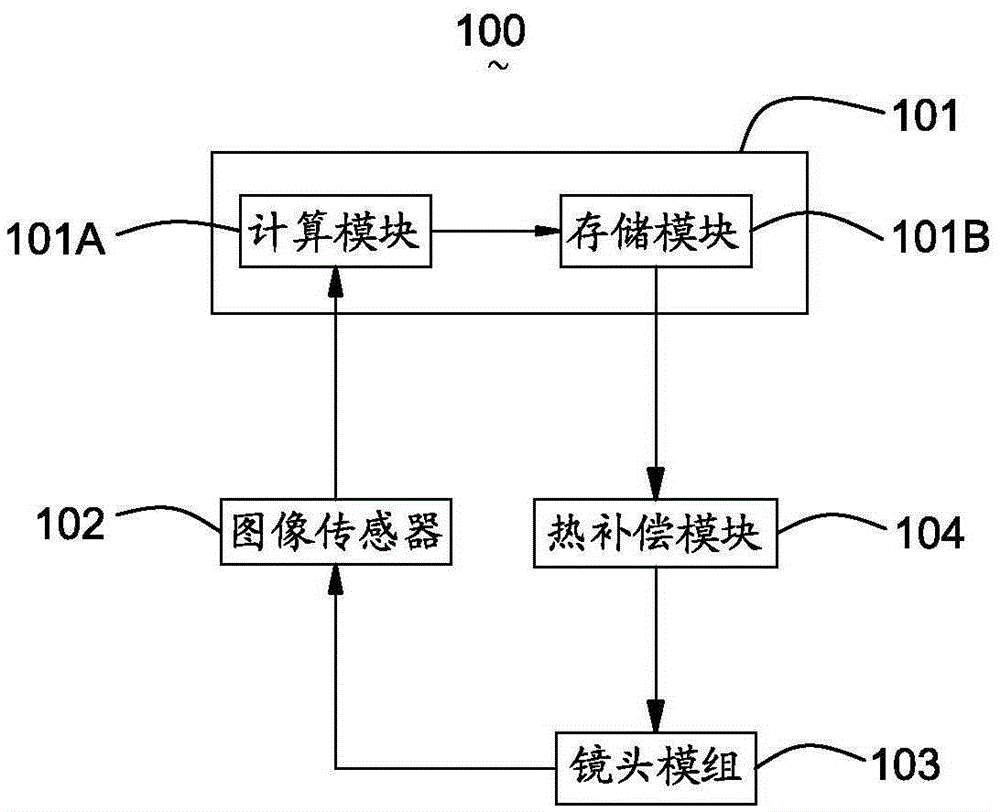
[0032] Such as figure 2 As shown, a camera lens 100 includes a central processing unit 101, an image sensor 102 electrically connected to the central processing unit 101, a lens module 103 electrically connected to the image sensor 102, and a thermal compensation module 104 electrically connected to the central processing unit 101 . The CPU 101 includes a calculation module 101A and a storage module 101B. The lens module 103 includes a first lens 105 and a second lens 106 .

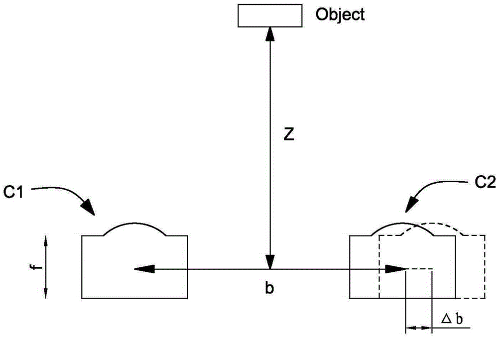
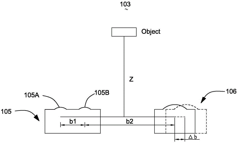
[0033] Such as image 3 As shown, the first lens 105 includes a focal length f1, which includes a glass substrate and a first lens unit 105A and a second lens unit 105B molded on the glass substrate. That is to say, the first lens 105 is a 1×2 integral glass lens. The base line length between the first lens unit 105A and the second lens unit 105B is b1. Since the first lens ...


PUM


Abstract

The invention provides a camera lens and a depth of field calibration method thereof. The camera lens comprises a lens module, a central processing unit and a thermal expansion compensation module, wherein the lens module comprises a first mirror and a second mirror being a baseline length b2 away from the first mirror; and the first mirror comprises a first lens unit molded on the same glass substrate with the first mirror, and a second lens unit being a baseline length b1 away from the first lens unit. The first mirror is made of glass, and has a relatively low thermal expansion coefficient, so that the baseline length between the first lens unit and the second lens unit is basically not influenced by temperature variations, and can be taken as a standard value of a depth of field. Based on the standard value, a variation value of the baseline length between the second mirror and the first mirror can be obtained by calculation, so that thermal expansion of the camera lens can be calibrated.

Description

【Technical field】 [0001] The invention relates to a camera lens for portable electronic equipment, in particular to a camera lens and a depth-of-field calibration method thereof. 【Background technique】 [0002] With the continuous development of technology, electronic devices are constantly developing toward intelligence. In addition to digital cameras, portable electronic devices such as tablet computers and mobile phones are also equipped with lens modules. In order to meet the needs of people, higher requirements are put forward for the image quality of the objects captured by the lens module. Moreover, with the development of 3D imaging technology, it has become a development trend to equip these mobile electronic devices with naked-eye 3D camera lenses. [0003] The 3D lens module in the related art adopts two groups of lens modules to imitate the imaging function of human eyes to take pictures with a certain depth of field. Such as figure 1 As shown, the related art...

Claims


Application Information

Patent Timeline
IPC IPC(8): H04N13/02H04N5/225
CPCH04N13/207H04N13/246H04N23/55
Inventor 帕列·吉尔特·丹森
Owner RUISHENG OPTOELECTRONICS TECH SUZHOU CO LTD
Why Eureka
Try Eureka