
freezer

A refrigeration device and refrigerant technology, applied in subcoolers, refrigerators, refrigeration components, etc., can solve problems such as poor cooling and insufficient refrigerant, and achieve the effects of suppressing overfilling and increasing costs

Active Publication Date: 2017-10-24
MITSUBISHI ELECTRIC CORP
View PDF9 Cites 0 Cited by
  • Summary
  • Abstract
  • Description
  • Claims
  • Application Information

AI Technical Summary

Problems solved by technology

In some manufacturer's instructions, this ratio is 5-10% relative to the amount of refrigerant sealed until the moment when the flash gas disappears. However, it has become the proprietary technology of each industry. Defective, therefore, it is often the case that a large amount of refrigerant is added

Method used


Image

  • freezer
  • freezer
  • freezer

Examples


Embodiment approach 1

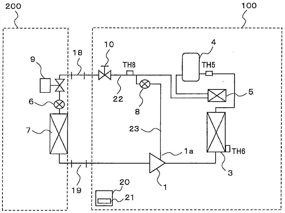
[0031] figure 1 It is a figure which shows an example of the refrigerant circuit of the refrigeration apparatus concerning Embodiment 1 of this invention.

[0032] The refrigeration system according to Embodiment 1 includes an outdoor unit 100 and an indoor unit 200 .

[0033] The outdoor unit 100 includes a compressor 1 , a condenser 3 , a liquid receiver 4 , and a subcooling heat exchanger 5 .

[0034] In addition, downstream of the subcooling heat exchanger 5, it is branched into a main flow path 22 going to the evaporator 7 of the indoor unit 200 and an injection flow path 23 going to the injection port 1a of the compressor 1, and a liquid operation is provided on the side of the main flow path 22. The valve 10 is provided with an expansion valve 8 on the side of the injection channel 23 . In addition, the indoor unit 200 is utilized by a showcase, a unit cooler, and the like.

[0035] The indoor unit 200 includes a liquid solenoid valve 9 , an expansion valve 6 , and ...

Embodiment approach 2

[0094] Figure 6 It is a figure which shows an example of the viewing windows 14 and 15 of the refrigeration apparatus concerning Embodiment 2 of this invention.

[0095] In addition, in this Embodiment 2, the difference with this Embodiment 1 is mainly demonstrated, and the same code|symbol is attached|subjected to the same part as this Embodiment 1, and description is abbreviate|omitted.

[0096] In Embodiment 2, a case will be described in which the refrigerant charge amount is confirmed by changing the position of the refrigerant liquid level 11 which is the largest throughout the year depending on the season, outside air temperature, high pressure, and the like.

[0097] In winter, etc., when the outside air temperature is low during the refrigerant charging operation, if the refrigerant is charged until the LED on the control board changes from N to O ( ) and the refrigerant liquid level 11 can be confirmed through the viewing window 14, the refrigerant may be charged ...


PUM


Abstract

A refrigeration device wherein a heat-source-side unit and a load-side unit are connected via liquid piping and gas piping, the heat-source-side unit having at least a compressor (1), a heat-source-side heat exchanger, a supercooling heat exchanger (5), and a liquid receiver (4), and the load-side unit having at least a load-side expansion means and a load-side heat exchanger. A refrigerant circuit is formed to circulate refrigerant in the compressor (1), the heat-source-side heat exchanger, the supercooling heat exchanger (5), the liquid receiver (4), the load-side expansion means, and the load-side heat exchanger. A sight glass (14) is provided to a side surface of the liquid receiver (4). The sight glass (14) is arranged at a position that enables confirmation of the position of the maximum liquid level (11) of the refrigerant in the liquid receiver (4) during operation throughout the year.

Description

technical field [0001] The present invention relates to freezing devices. Background technique [0002] In the past, in the refrigeration equipment used for cooling supermarket showcases, cooling refrigerated warehouses by unit coolers, etc., showcases were mainly installed in food stores, but the number, size, type, arrangement, etc. Depending on the store, the internal volume of the evaporator arranged in the showcase also varies. In addition, the volume of the evaporator of the unit cooler also differs depending on the type and the like, and this is also the same. In addition, the installation location of the refrigerator that houses the compressor, the condenser, and the liquid receiver also varies depending on the structure of the store. For example, it may be installed on the backside or on the roof of a food store. For this reason, the distance between the evaporator, the compressor, the condenser, and the liquid receiver varies depending on the installation locatio...

Claims


Application Information

Patent Timeline
Patent Type & Authority Patents(China)
IPC IPC(8): F25B49/02F25B43/00
CPCF25B49/02F25B40/02F25B41/006F25B45/00F25B2400/13F25B2400/16F25B2500/01F25B2500/23F25B2500/24F25B2700/2106F25B2700/21162F25B2700/21163
Inventor 佐多裕士落合康敬玉木章吾
Owner MITSUBISHI ELECTRIC CORP
Learn More