Ophthalmic operation system

A technology of ophthalmic surgery and control unit, which is applied in ophthalmic surgery, medical science, diagnosis, etc. It can solve the problems of imperfect ophthalmic treatment system, no surgical treatment system, and low work efficiency, and achieve simple structure, easy operation, and guaranteed smooth effect

Inactive Publication Date: 2016-03-23
JILIN UNIV
View PDF6 Cites 3 Cited by
  • Summary
  • Abstract
  • Description
  • Claims
  • Application Information

AI Technical Summary

Problems solved by technology

[0002] Current ophthalmic surgery systems provide surgical instruments connected to one or more consoles. The surgical instruments are often electrically or pneumatically operated. The consoles provide electrical or hydraulic control signals to operate the instruments. The consoles typically have several different types of manual controls. The platform is used to generate control signals for surgical instruments. A lot of inspections and preparations are often carried out during ophthalmic surgery. Now patients need to go to different departments for inspections before surgery, so the work efficiency is very low. It does not have a complete set of surgical treatment system; in addition, because there are very few eye diseases, doctors will make preliminary judgments based on clinical cases before performing eye surgery, but the current ophthalmic treatment system of the hospital is not perfect in this respect On the other hand, one of the most common forms of anesthesia administration is the intravenous route, which can be intermittent intravenous injection or continuous intravenous injection. Anesthetic drugs are usually transported in bottled containers. In order to facilitate the management of intravenous injection, anesthetic drugs must be loaded into For syringes of different sizes, these bottles are generally marked manually, and the anesthetic is injected according to the experience value. The workload is heavy and the accuracy is poor. During the anesthesia process, the anesthetic cannot be input in real time according to the patient's vital signs.

Method used


Image

  • Ophthalmic operation system

Examples


Embodiment Construction

[0014] The preferred embodiments of the present invention will be described below in conjunction with the accompanying drawings. It should be understood that the preferred embodiments described here are only used to illustrate and explain the present invention, and are not intended to limit the present invention.

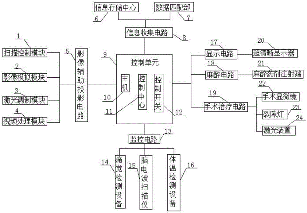
[0015] Such as figure 1 As shown, an ophthalmic surgery system of the present invention includes a control unit 9 and a host 10, a control center 11 and a control switch 12 arranged in the control unit 9, the control unit 9 is electrically connected to the image auxiliary projection circuit 5, and the The image auxiliary projection circuit 5 includes a scanning control module 1, an image simulation module 2, a laser modulation module 3 and a video processing module 4. The control unit 9 is electrically connected to a monitoring circuit 13, and the monitoring circuit 13 includes pain detection equipment, brain wave Scanner and body temperature detection equipment 14,...


PUM


Abstract

The invention discloses an ophthalmic operation system, which comprises a control unit as well as a hot machine, a control center and a control switch which are arranged inside the control unit, wherein the control unit is electrically connected to an auxiliary image projection circuit; the auxiliary image projection circuit comprises a scanning control module, an image simulation module, a laser modulation module and a video processing module; the control unit is electrically connected to a monitoring circuit; the monitoring circuit comprises pain sense detection equipment, a brainwave scanner and body temperature detection equipment; the control unit is electrically connected to an information collection circuit; the information collection circuit comprises an information memory center and a data matching part; the control unit is electrically connected to a display circuit; the display circuit comprises an ultra-clear display; the control unit is electrically connected to an anesthesia circuit; and the anesthesia circuit comprises an anesthetic agent injection end. The ophthalmic operation system is reasonable in design and high in intelligence degree, and the ophthalmic operation system is capable of effectively guaranteeing the smooth implementation of an operation.

Description

technical field [0001] The invention relates to the technical field of ophthalmic systems, in particular to an ophthalmic operation system. Background technique [0002] Current ophthalmic surgery systems provide surgical instruments connected to one or more consoles. The surgical instruments are often electrically or pneumatically operated. The consoles provide electrical or hydraulic control signals to operate the instruments. The consoles typically have several different types of manual controls. The platform is used to generate control signals for surgical instruments. A lot of inspections and preparations are often carried out during ophthalmic surgery. Now patients need to go to different departments for inspections before surgery, so the work efficiency is very low. It does not have a complete set of surgical treatment system; in addition, because there are very few eye diseases, doctors will make preliminary judgments based on clinical cases before performing eye sur...

Claims


Application Information

Patent Timeline
Patent Type & Authority Applications(China)
IPC IPC(8): A61F9/007A61B5/00A61B5/01A61B5/0476A61M5/14
Inventor 许卉宗珊李海亮
Owner JILIN UNIV
Why Eureka
Try Eureka