Centrifuge for automatically separating pulp and dregs

An automatic separation and centrifuge technology, applied in the field of centrifuges, can solve problems such as frequent shutdowns and affect work efficiency, and achieve the effects of improving work efficiency, prolonging life, and preventing burnout

Inactive Publication Date: 2016-03-23
ANHUI HUAIHUA
View PDF7 Cites 4 Cited by
  • Summary
  • Abstract
  • Description
  • Claims
  • Application Information

AI Technical Summary

Problems solved by technology

The material that has lost its liquid content will adhere to the filter screen on the inner wall of the drum layer by layer. With the increase of the feed amount, the material attached to the inner wall of the drum will also

Method used


Image

  • Centrifuge for automatically separating pulp and dregs

Examples


Embodiment Construction

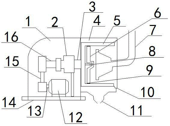
[0017] refer to figure 1 As shown, a centrifuge for automatic separation of pulp and residue includes a machine compartment 1 for fixing a gearbox 2 and a stepper motor 12 and a liquid collection bin 4 for filtering, and the stepper motor 12 passes through a driven shaft 16 Connected with the gearbox 2, a liquid outlet 11 is provided directly below the liquid collection bin 4, and a feed pipe 7 for transferring materials is provided outside the liquid collection bin 4, and the output end of the gearbox 2 passes through the rotating shaft 3 is connected with the filter frame 5 located in the liquid collection bin 4, and drives the filter frame 5 to rotate; the filter frame 5 is a frame-shaped structure with an outer end opening and a filter screen in the middle, and the output end of the feed pipe 7 is from The opening end of the filter frame 5 protrudes into the filter frame 5 ; a slag outlet 10 is provided at the bottom of the liquid collection bin 4 outside the opening end o...


PUM


Abstract

The invention discloses a centrifuge for automatically separating pulp and dregs. The centrifuge comprises a machine bin for fixing a gearbox and a stepping motor, and a liquid collecting bin for filtering, wherein the stepping motor is connected to the gearbox through a driven shaft; a liquid outlet is formed right below the liquid collecting bin; a feeding tube for conveying a material is arranged at the outer side of the liquid collecting bin; the output end of the gearbox is connected to a filtering frame in the liquid collecting bin through a rotating shaft, so that the gearbox drives the filtering frame to rotate; the filtering frame has a frame structure of which the outer end is provided with an opening and the middle is provided with a filtering screen; the output end of the feeding tube extends into the filtering frame from the opening end of the filtering frame; a dreg outlet is formed in the bottom part of the liquid collecting bin at the outer part of the opening end of the filtering frame. According to the centrifuge, a washing plate reciprocates in the filtering frame, so that the material on the filtering screen can be removed without stopping the centrifuge, and as a result, the working efficiency can be greatly improved.

Description

technical field [0001] The invention relates to a centrifuge, in particular to a centrifuge for automatic separation of pulp and residue. Background technique [0002] Centrifuges are widely used in chemical, pharmaceutical, food and other industries, mainly for separating or drying liquid components in materials. [0003] The structure of the existing centrifuge is as follows: a cylindrical drum is arranged in the casing, filter holes are opened on the side wall of the drum, a filter screen is arranged on the inner wall of the drum, the drum is arranged on the main shaft, and the main shaft Driven by the driving device to run at high speed, the feeding device is installed on the machine cover. When working, the material that needs to be removed from the liquid component is introduced into the drum by the feeding device, and the high-speed rotating drum throws the liquid component in the material out of the drum, so as to achieve the purpose of solid-liquid separation. T...

Claims


Application Information

Patent Timeline
IPC IPC(8): B04B1/00B04B15/06B04B9/02
CPCB04B1/00B04B9/02B04B15/06
Inventor 张元春
Owner ANHUI HUAIHUA
Why Eureka
Try Eureka