Part cleaning machine

A cleaning machine and parts technology, applied in the field of cleaning machines, can solve the problems of unreasonable layout, large occupied space, and unfavorable utilization of the internal space of the factory building, etc., and achieve good heat preservation effect, high work efficiency, and reasonable layout of the body structure

Pending Publication Date: 2016-03-23
TAIZHOU QUAN QIU YING IND & TRADE
View PDF11 Cites 4 Cited by
  • Summary
  • Abstract
  • Description
  • Claims
  • Application Information

AI Technical Summary

Problems solved by technology

However, the overall structure of the washing machine body is poor in compactness, unreasonable in layout, and occupies a relatively large space, which is not conducive to the full utilization of the internal space of the factory building.

Method used


Image

  • Part cleaning machine
  • Part cleaning machine
  • Part cleaning machine

Examples


Embodiment Construction

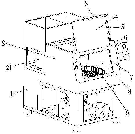
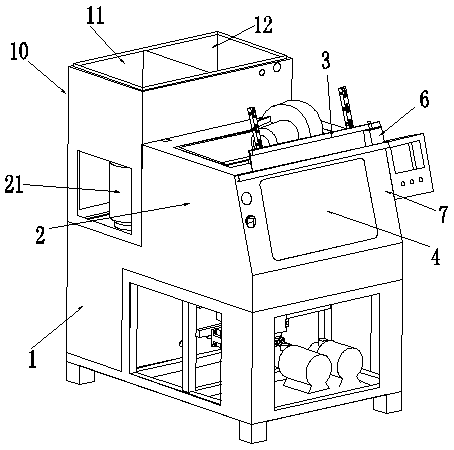
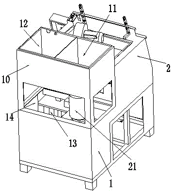
[0021] As shown in the figure, the structure of the parts cleaning machine includes a cleaning tank 2 and a liquid storage tank 1, and the cleaning tank 2 is located at the oblique top of the liquid storage tank 1. A power mechanism is provided below the cleaning box 2, and a cleaning frame 9 is arranged in the cleaning box 2. The power mechanism extends into the cleaning box 2 and is connected with the cleaning frame 9. The power mechanism is used to drive the cleaning frame 9 in the cleaning box 2. turn.

[0022] The bottom plate of the cleaning tank 2 and the top plate of the liquid storage tank 1 are generally connected as a whole. To be higher than the outer top surface of the liquid storage tank 1. In order to facilitate the flow of cleaning liquid, the inner bottom surface of the cleaning box 2 can be obliquely above the outer top surface of the liquid storage tank 1, and the inner bottom surface of the cleaning box 2 is inclined. A liquid flow channel is provided bet...


PUM


Abstract

The invention discloses a part cleaning machine and solves the problem that the conventional cleaning machine has poor structural compactness and easily occupies overlarge indoor space. The technical scheme adopted in the invention is as follows: a machined part cleaning machine comprises a cleaning box, a liquid storage box and a filter unit, wherein a cleaning rack is arranged in the cleaning box; a power mechanism is in transmission connection with the cleaning rack; the liquid storage box communicates with the filter unit through a water pump and a pipeline; a water pump motor is in transmission connection with the water pump; the cleaning box is located above the liquid storage box; the power mechanism is located below the cleaning box; the inner bottom surface of the cleaning box is at least flush with the outer top surface of the liquid storage box; a filter port is formed in a top plate of the liquid storage box; a basket type filter screen is arranged in the filter port; an open type liquid flow passage is arranged between the inner bottom surface of the cleaning box and the outer top surface of the liquid storage box; the liquid flow passage leads to the filter port; the filter unit is located above the liquid flow passage; and a liquid outlet of the filter unit faces the liquid flow passage and is used for flushing the bottom surface of the liquid flow passage.

Description

technical field [0001] The invention relates to a cleaning machine, in particular to a parts cleaning machine for cleaning parts including machining. Background technique [0002] During the machining process, the machined parts usually need to be applied with a lubricant. Due to the adhesion of the lubricant, the metal fines generated during the machining process, as well as the impurities in the outside world, will adhere to the machined parts. superior. Therefore, the machined parts usually need to be cleaned before they can be assembled on the complete machine, otherwise the fine particles attached to the parts will affect the assembly and work of the complete machine. The relatively primitive parts cleaning method is carried out manually. The operation speed of manual cleaning is slow, the labor intensity is high, and the consumption of cleaning fluid is large. [0003] Cleaning machines have also appeared on the existing market. For the convenience of recycling the c...

Claims


Application Information

Patent Timeline
Patent Type & Authority Applications(China)
IPC IPC(8): B08B3/10B08B3/14B08B13/00
CPCB08B3/041B08B3/10B08B3/14B08B13/00
Inventor 阮锦华
Owner TAIZHOU QUAN QIU YING IND & TRADE
Why Eureka
Try Eureka