Eureka AIR delivers breakthrough ideas for toughest innovation challenges, trusted by R&D personnel around the world.

Movable welding platform used for transverse and longitudinal joints of guiding pipe pile

A movable platform, horizontal and vertical seam technology, applied in welding equipment, auxiliary welding equipment, welding/cutting auxiliary equipment, etc., can solve the problems of increasing structural manufacturing cost, large volume, weight, inconvenient use, etc., and achieve reasonable structural design. , The effect of high safety performance and convenient movement

Inactive Publication Date: 2016-03-23
NANTONG BLUE ISLAND OFFSHORE CO LTD
View PDF17 Cites 1 Cited by
  • Summary
  • Abstract
  • Description
  • Claims
  • Application Information

AI Technical Summary

Problems solved by technology

[0003] The traditional welding platform mainly has the following structures: (1) A standing seam welding frame with four corners of the box mentioned in the invention of the patent No. 200720175055.1. Very difficult and inconvenient to use; (2) The fixed structure built by a simple steel frame cannot adapt to the change of the weld position, the structural design is inflexible, inconvenient to use and poor in work efficiency; (3) The lifting or rotating structure driven by external force, Horizontal movement is controlled by increasing the distance in the horizontal direction of the structure, which makes the structure of the device larger in size and weight, making it extremely inconvenient to move. At the same time, the drive of external force makes the structure more complicated and increases the manufacturing cost of the structure; therefore, it is urgent to develop a structure with reasonable and flexible design. The movable platform for the transverse and longitudinal seam welding of conduit piles with low manufacturing cost has not been found to have the same or similar technical solutions as the present invention

Method used


Image

  • Movable welding platform used for transverse and longitudinal joints of guiding pipe pile
  • Movable welding platform used for transverse and longitudinal joints of guiding pipe pile

Examples


Embodiment Construction

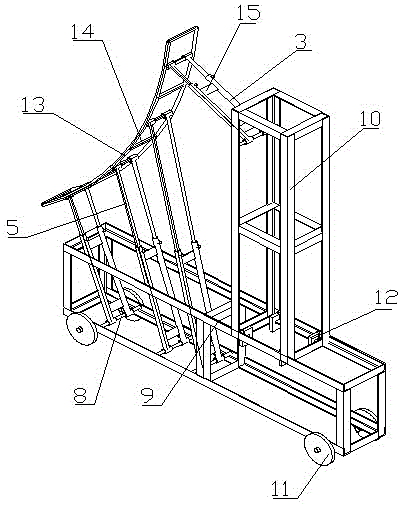
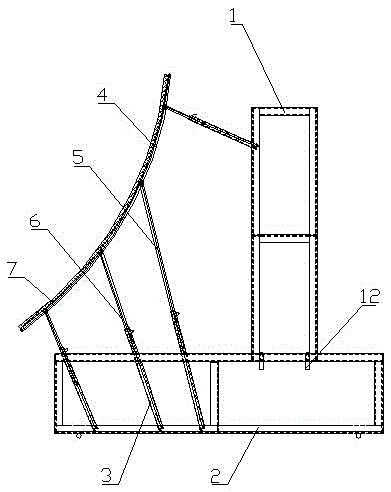
[0019] Such as figure 1 with figure 2 As shown, the invention discloses a movable platform for transverse and longitudinal seam welding of conduit piles, which includes a pair of vertical and parallel support frames, a working platform erected on the support frames and a ladder connected to the support frames.

[0020] The support frame includes a pair of steel pipes A1 arranged in parallel at the lower end, a pair of steel pipes B3 fitted on the upper part of the steel pipe A1 and fixed with a movable pin A, and a strengthening device arranged between the steel pipe A1 and the steel pipe B3; the upper end of the steel pipe A1 along the axial direction Set a number of through holes A2 horizontally passing through the opposite side walls of the steel pipe A1; set a number of through holes B4 horizontally passing through the opposite side walls of the steel pipe B3 along the axial direction at the lower end of the steel pipe B3, and the through holes B4 and the through holes A2...


PUM


Abstract

The invention relates to a movable welding platform used for transverse and longitudinal joints of guiding pipe piles. The movable welding platform comprises a pair of parallel support frames and a working platform erected on the support frames, wherein the support frames comprise a pair of parallel steel pipes A arranged at the lower end, a pair of steel pipes B which are arranged on the upper parts of the steel pipes A in an inserted and matched manner and are fixed with movable pins A and reinforcing devices arranged between the steel pipes A and the steel pipes B; and the working platform comprises a lower-layer horizontal platform and an upper-layer horizontal platform which are nested and matched with each other, a guard rail A which is arranged on the lower-layer horizontal platform and is formed by connecting a plurality of tubular structures and a guard rail B which is arranged on the upper-layer horizontal platform and is formed by connecting a plurality of tubular structures. The movable welding platform has the advantages that the length and height of the movable welding platform used for the transverse and longitudinal joints of the guiding pipe piles in the horizontal direction and the vertical direction can be adjusted according to the positions of to-be-welded welding joints; during the adjustment process, a worker only needs to enable through holes A to correspond to through holes B, enable through holes C to correspond to through holes D, and fix with the movable pins A and movable pins B separately; the structure design is reasonable; and adjustment is convenient.

Description

technical field [0001] The invention relates to a welding movable platform, in particular to a movable platform for welding transverse and longitudinal seams of conduit piles. Background technique [0002] The welding movable platform is a device for operators to climb for the welding of large components. Since the structure of the pipe pile used in large devices such as bridges is relatively large, it must have a complete support device. [0003] The traditional welding platform mainly has the following structures: (1) A standing seam welding frame with four corners of the box mentioned in the invention of the patent No. 200720175055.1. Very difficult and inconvenient to use; (2) The fixed structure built by a simple steel frame cannot adapt to the change of the weld position, the structural design is inflexible, inconvenient to use and poor in work efficiency; (3) The lifting or rotating structure driven by external force, Horizontal movement is controlled by increasing ...

Claims


Application Information

Patent Timeline
IPC IPC(8): B23K37/00
CPCB23K37/00
Inventor 孙其权
Owner NANTONG BLUE ISLAND OFFSHORE CO LTD
Why Eureka
Eureka Blog
Learn More