Conveying and clamping device for counting type drill rod auxiliary machining

A clamping device and auxiliary processing technology, which is applied in the direction of positioning devices, metal processing equipment, metal processing machinery parts, etc., can solve the problems of inconvenient use, inconvenient processing, inconvenient transportation, etc., and achieve convenient use, low cost, and convenient post-management Effect

Inactive Publication Date: 2016-03-23
WUXI ZHONGDI DRILLING EQUIP
View PDF7 Cites 4 Cited by
  • Summary
  • Abstract
  • Description
  • Claims
  • Application Information

AI Technical Summary

Problems solved by technology

For long drill pipes, such as oil drill pipes, due to their long length, mostly more than a few meters, it is inconvenient to process. The structure of the auxiliary clamping device currently used is complicated and inconvenient to use. For example, it can only be clamped, and it is not convenient for transportation. Wait

Method used


Image

  • Conveying and clamping device for counting type drill rod auxiliary machining
  • Conveying and clamping device for counting type drill rod auxiliary machining
  • Conveying and clamping device for counting type drill rod auxiliary machining

Examples


Embodiment Construction

[0015] The specific embodiments of the present invention will be further described below in conjunction with the accompanying drawings.

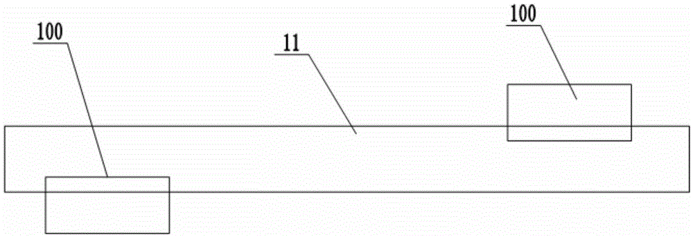
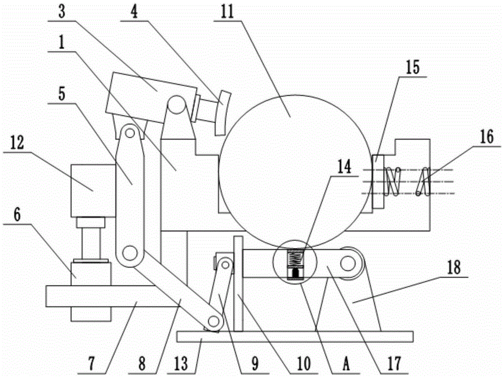
[0016] Such as figure 1 , figure 2 As shown, in the conveying and clamping device of the counting drill pipe auxiliary processing in this embodiment, the two clamping devices 100 are located at both ends of the drill rod 11; And the auxiliary support seat 2, the drill pipe 11 is placed between the main support seat 1 and the auxiliary support seat 2, the ejection guide roller 17 is arranged under the drill pipe 11, and the swing type clamping hydraulic cylinder 3 is hinged on the upper end of the main support seat 1 , the piston rod of the swing-type clamping hydraulic cylinder 3 is equipped with a clamping block 4 facing the drill pipe 11, and the outside of the main support base 1 is provided with a lifting connecting plate 5, and the upper end of the lifting connecting plate 5 is connected to the swinging clamping hydraulic cylinder 3 ...


PUM


Abstract

The invention relates to a conveying and clamping device for counting type drill rod auxiliary machining. Two clamping device bodies are located at the two ends of a drill rod. Each clamping device body comprises a main supporting seat and an auxiliary supporting seat which are transversely and symmetrically arranged in a spaced manner. The drill rod is placed between the main supporting seats and the auxiliary supporting seats. Ejection guide rollers are arranged below the drill rod and induction counting devices are installed on the ejection guide rollers. Swing type clamping hydraulic cylinders are hinged to the upper ends of the main supporting seats. Clamping blocks are installed on piston rods of the swing type clamping hydraulic cylinders. Lifting connecting boards are arranged on the outer sides of the main supporting seats. The upper ends of the lifting connecting boards are hinged to the swing type clamping hydraulic cylinders and the lower ends of the lifting connecting boards are connected with the ends of the ejection guide rollers. One end of each ejection guide roller is vertically installed on a sliding supporting frame in a sliding manner and the other end of each ejection guide roller is connected with a hinge seat. Vertical hydraulic cylinders are installed on the side faces of the lifting connecting boards. Abutting boards are installed on the inner sides of the auxiliary supporting seats through springs. The two main supporting seats and the two auxiliary supporting seats at the two ends of the drill rod are oppositely located on the two sides of the drill rod respectively.

Description

technical field [0001] The invention relates to the technical field of geological exploration, in particular to a processing device for drill pipes. Background technique [0002] The drill rod is a rod-shaped or tubular part that transmits power to the drill bit and enters the drill hole with the drill bit. It is an important part of the drilling machine. The drill pipe is made of light pipe and original steel pipe after many times of processing. For long drill pipes, such as oil drill pipes, due to their long length, mostly more than a few meters, it is inconvenient to process. The structure of the auxiliary clamping device currently used is complicated and inconvenient to use. For example, it can only be clamped, and it is not convenient for transportation. Wait. Contents of the invention [0003] Aiming at the above-mentioned shortcomings of the prior art, the applicant conducts research and improvement, and provides a conveying and clamping device for counting drill ...

Claims


Application Information

Patent Timeline
Patent Type & Authority Applications(China)
IPC IPC(8): B23Q3/08B23Q3/10B23Q17/00
CPCB23Q3/082B23Q3/064B23Q3/103B23Q17/00
Inventor 苏刚
Owner WUXI ZHONGDI DRILLING EQUIP
Why Eureka
Try Eureka