
Exhausting insert core of mold

A technology of mold and exhaust sheet, which is applied in the field of exhaust entry of molds, can solve problems such as easy dislocation of shapes, and achieve the effect of improving efficiency and avoiding mold repairs.

Inactive Publication Date: 2016-03-23
MITAC PRECISION TECH(KUNSHAN) CORP
View PDF5 Cites 1 Cited by
  • Summary
  • Abstract
  • Description
  • Claims
  • Application Information

AI Technical Summary

Problems solved by technology

[0005] Therefore, the purpose of the present invention is to provide a kind of exhaust inlet of the mold, to solve the problem that the exhaust inlet in the prior art is connected in series by several exhaust sheets, and the cumulative tolerance is caused by the tolerance of each exhaust sheet. The problem that the shape formed by the molding structure on each exhaust piece is easily misplaced

Method used


Image

  • Exhausting insert core of mold
  • Exhausting insert core of mold
  • Exhausting insert core of mold

Examples


Embodiment Construction

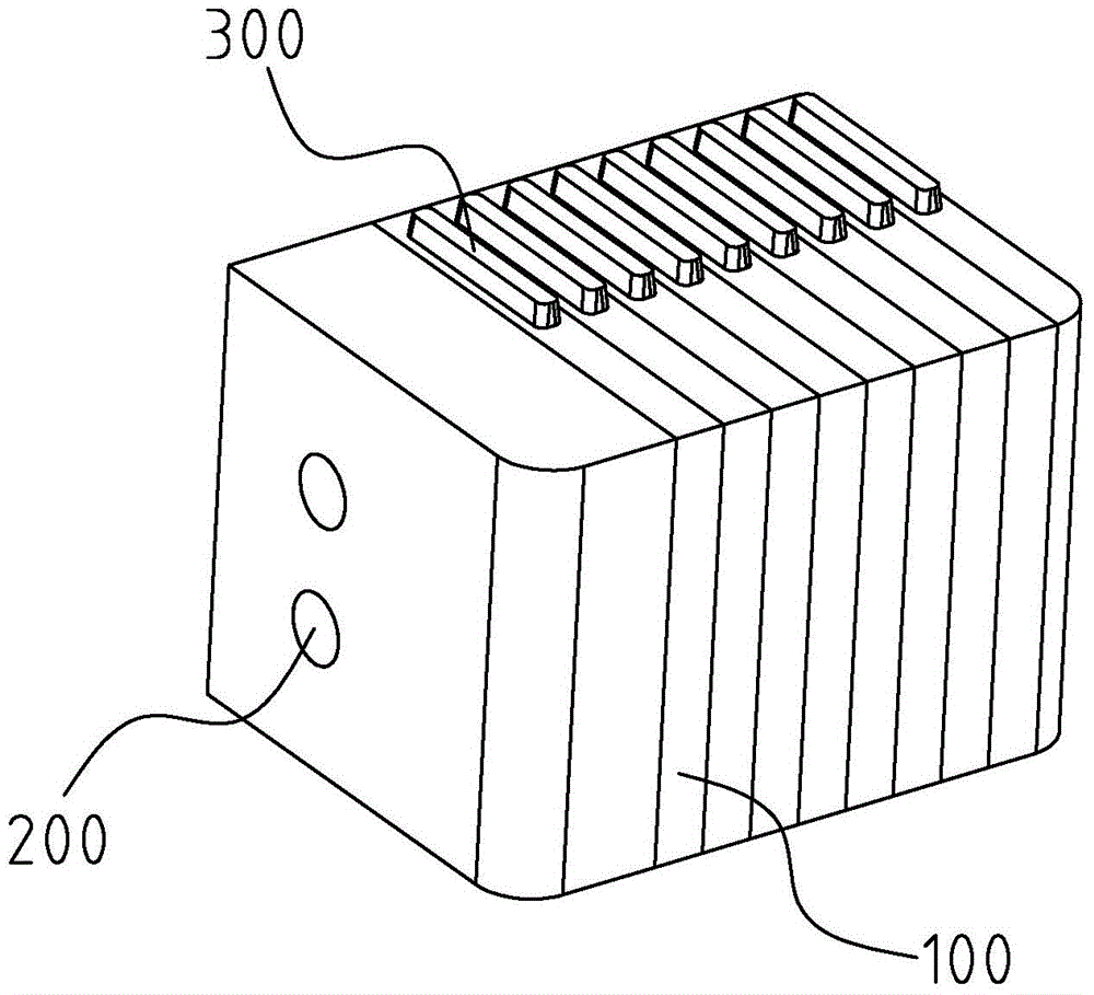
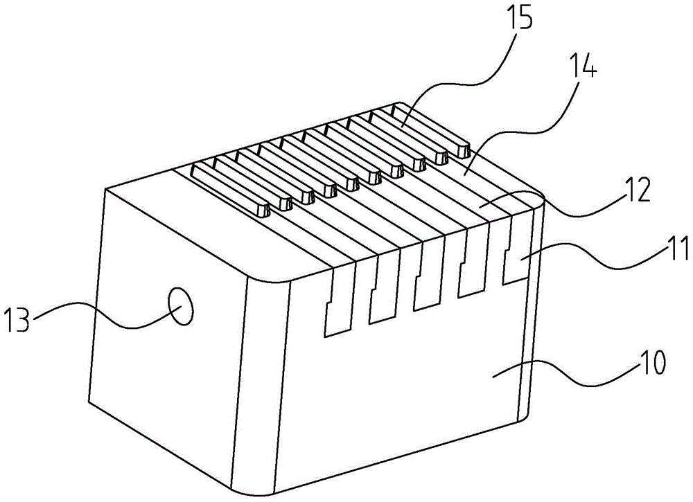
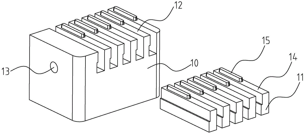
[0017] Please refer to figure 2 , image 3 , figure 2 It is a schematic structural view showing a preferred embodiment of the exhaust inlet of the mold of the present invention, image 3 It is a schematic exploded structure diagram of a preferred embodiment of the exhaust inlet of the mold of the present invention.

[0018] In order to achieve the above object, the exhaust inlet of the mold provided by the present invention includes:

[0019] The exhaust base 10 is provided with several slots 11 and several base exhaust sheets 12 at intervals, and the exhaust base 10 is along a direction perpendicular to the plane where the base exhaust sheet 12 is located. A through exhaust hole 13 is opened, and the exhaust hole 13 communicates with the bottom of the slot 11, and the effect of exhaust is achieved through the exhaust hole 13;

[0020] A plurality of independent air vents 14 are respectively arranged in the above-mentioned one slot 11 .

[0021] Wherein, there is a hang...


PUM


Abstract

The invention discloses an exhausting insert core of a mold. The exhausting insert core comprises an exhausting base and a plurality of independent exhausting pieces. The exhausting base is provided with a plurality of grooves at intervals and a plurality of base exhausting pieces. A penetrating exhausting hole is formed on the exhausting base, in the direction perpendicular to the plane where the base exhausting pieces are located. The exhausting hole is communicated with the bottoms of the grooves. All the independent exhausting pieces are arranged in the corresponding grooves. Due to the fact that the number of the independent exhausting pieces is reduced to be half of the previous number, the base exhausting pieces are integrally machined through the exhausting base, and the base exhausting pieces are mutually independent, so that accumulated tolerance is avoided; the independent exhausting pieces are arranged in the grooves respectively, and accumulated tolerance among the independent exhausting pieces is also avoided. Accordingly, the accumulated tolerance among all the exhausting pieces is not produced, and a forming structure arranged on the exhausting pieces does not produce accumulated tolerance, and thus dislocation of bodies of corresponding parts of produced products is avoided, mold repair is also avoided, and the efficiency is improved.

Description

【Technical field】 [0001] The invention relates to a mould, in particular to an exhaust inlet of a mould. 【Background technique】 [0002] During injection molding of plastic products, gas is generated in the mold cavity with the injection of molten plastic liquid. The gas mainly includes: the air existing in the mold cavity and the gating system, and the moisture contained in the plastic raw materials evaporated at high temperature. The water vapor produced, the gas produced by the decomposition of plastic at high temperature and the gas produced by the volatilization of certain additives in plastic. During injection molding, if these gases cannot be discharged from the mold cavity in time, these gases will cause many problems such as pores, air marks, cavities, burnt, and bubbles on the surface of the product when the product is molded. [0003] see figure 1 , figure 1 It is a structural schematic diagram of an exhaust inlet of a mold in the prior art. The exhaust inlet ...

Claims


Application Information

Patent Timeline
IPC IPC(8): B29C45/34
Inventor 石磊
Owner MITAC PRECISION TECH(KUNSHAN) CORP
Learn More