
Cantilever type hydraulic lifting bi-directional belt conveyor

A hydraulic lifting, two-way conveying technology, applied in the direction of conveyors, conveyor objects, transportation and packaging, etc., can solve the problems of V-belt slippage, belt conveyor can not effectively extend into the wagon, conveyor straddle collapse and other problems, to prevent slippage Effect

Inactive Publication Date: 2016-03-23
YIDU LINLONG MINING MACHINERY
View PDF6 Cites 5 Cited by
  • Summary
  • Abstract
  • Description
  • Claims
  • Application Information

AI Technical Summary

Problems solved by technology

[0002] During the loading and unloading process of the traditional belt conveyor, the reducer and the wire rope drive the lever to lift up and down. At the same time, due to the lever, the belt conveyor cannot effectively extend into the wagon, and the lifting system of the existing conveyor is driven by the winding machine. The head and tail begin to change, not only occupying a large area, but also the steel wire rope is severely worn, and the steel wire rope is often corroded and short-cracked, resulting in the collapse of the conveyor. It is troublesome to replace and maintain the steel wire rope
On the other hand, the driving configuration of the traditional conveyor is not suitable for feeding materials at a large inclination angle. , and when the equipment is running with load, the V-belts on the large and small pulleys will slip, that is, the pulley at the running end of the motor rotates, but the corresponding pulley of the equipment does not move

Method used


Image

  • Cantilever type hydraulic lifting bi-directional belt conveyor
  • Cantilever type hydraulic lifting bi-directional belt conveyor
  • Cantilever type hydraulic lifting bi-directional belt conveyor

Examples


Embodiment Construction

[0021] The following is a further description of the utility model in conjunction with the drawings:

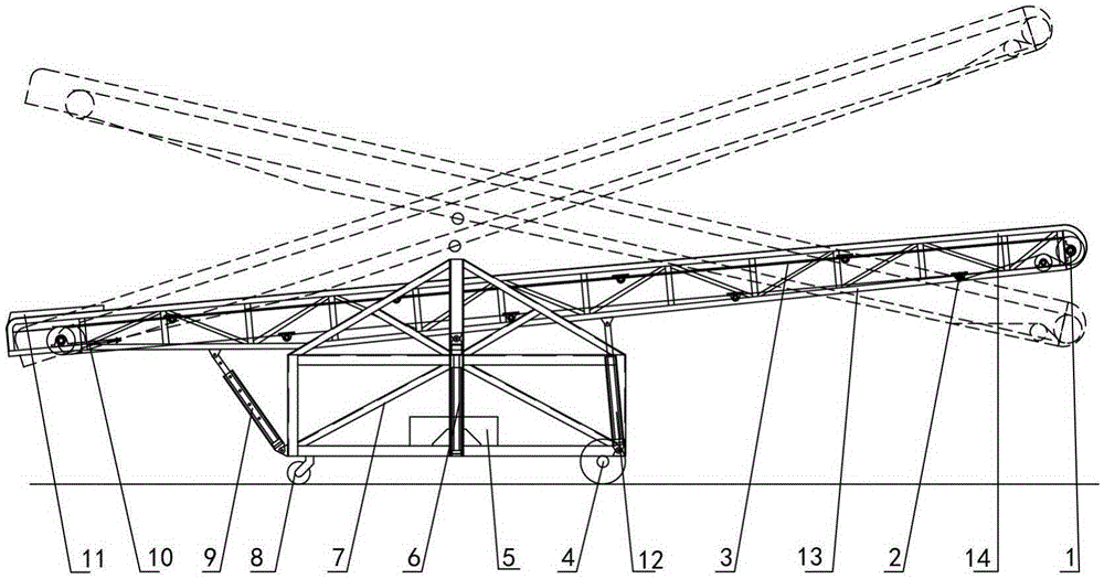
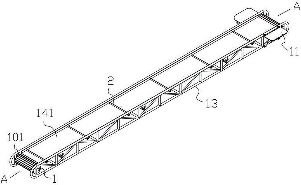
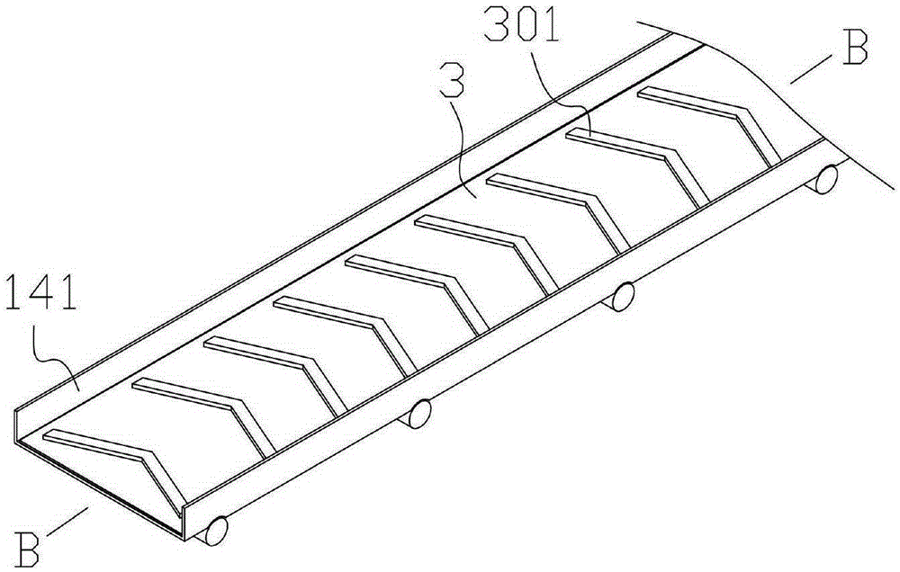
[0022] In the picture: electric drum 1, idler 2, conveyor belt 3, rubber roller 4, hydraulic oil tank 5, first hydraulic cylinder 6, movable support 7, universal roller 8, safety rod 9, tension device 10, movable springboard 11 , Second hydraulic cylinder 12, frame 13, wear-resistant rubber 101, engraved horizontal strip 102, anti-skid iron plate 111, support rod 112, protrusion 301, steel groove 141, opening 142, positioning sleeve 901, positioning rod 902, positioning 孔903.

[0023] Such as Figure 1 to 9 As shown, the cantilever hydraulic lifting belt two-way conveyor includes a movable support 7 and a conveying mechanism. A rubber roller 4 and a universal roller 8 are installed at the lower end of the support 7, and it also includes a safety rod 9, a first hydraulic cylinder 6 and a second hydraulic Cylinder 12, the conveying mechanism is connected to the mobile support 7 thr...


PUM


Abstract

A cantilever type hydraulic lifting bi-directional belt conveyor comprises a movable support and a conveying mechanism; rollers are installed at the lower end of the support; the belt conveyor further comprises a safety rod, a first hydraulic cylinder and a second hydraulic cylinder; the conveying mechanism is connected with the movable support through the safety rod, the first hydraulic cylinder and the second hydraulic cylinder; two ends of both the safety rod and the second hydraulic cylinder are hinged to the conveying mechanism and the movable support respectively; one end of the first hydraulic cylinder is connected onto the support fixedly, and the other end of the first hydraulic cylinder is hinged to the conveying mechanism; the first hydraulic cylinder is located between the safety rod and the second hydraulic cylinder; and one end of the first hydraulic cylinder is hinged to the middle portion of the conveying mechanism. The belt conveyor can effectively stretch into a railway carriage, and the railway carriage can be loaded or unloaded. When an inclined angle of the conveyor is enlarged, a conveyed material is not prone to slipping.

Description

Technical field [0001] The invention relates to a belt conveyor, in particular to a cantilever type hydraulic lifting belt two-way conveyor. Background technique [0002] In the process of loading and unloading wagons, traditional belt conveyors use the reducer and steel wire rope to drive the lever to lift. At the same time, due to the lever, the belt conveyor cannot effectively extend into the wagon, and the existing conveyor lifting system drives the steel wire rope by the winding machine. The head and tail began to change, not only occupying a large area, but also the steel wire rope is severely worn, and the steel wire rope is often corroded and short-cracked, which leads to the collapse of the conveyor and the replacement and maintenance of the wire rope is troublesome. On the other hand, the drive configuration of the traditional conveyor is not suitable for large inclination feeding. The main reason is that the drive principle of the traditional conveyor is a combination ...

Claims


Application Information

Patent Timeline
IPC IPC(8): B65G21/12B65G15/58B65G23/04B65G23/44B65G39/10
CPCB65G15/58B65G21/12B65G23/04B65G23/44B65G39/10
Inventor 王飞邓爱国邓绍林许松
Owner YIDU LINLONG MINING MACHINERY
Learn More