Construction method of high-fill prefabricated cast-in-situ combined pile slab wall protection structure

A technology for protective structures and construction methods, which is applied in basic structure engineering, underwater structures, artificial islands, etc., can solve the problems of large number of drilling holes and grouting works, insufficient self-stability, slow construction progress, etc. The effect of short construction period, collapse prevention and strong applicability

Active Publication Date: 2016-03-23
杭州市交通规划设计研究院有限公司
View PDF7 Cites 26 Cited by
  • Summary
  • Abstract
  • Description
  • Claims
  • Application Information

AI Technical Summary

Problems solved by technology

Among them, the reinforced earth retaining wall has the performance of a flexible structure, and can be built into a relatively high vertical fill. It has the advantages of small footprint, light structure, less settlement, and simple construction. However, it is not suitable for alpine landslides and collapsed sections. Larger potential safety hazards; anchor rods and anchor plate retaining walls have small self-weight, reasonable structure, and are conducive to mechanized construction, but the installation of anchor cables is large, resulting in a large number of drilling holes and grouting engineering, and slow construction progress. Moreover, its own stability is insufficient under high filling conditions; the reinforced concrete cantilever retaining wall also has a large safety hazard in the alpine cantilever section
[0004] In summary, although the existing pile-slab wall structure can achieve good results under suitable engineering conditions, there are still some areas for improvement.

Method used


Image

  • Construction method of high-fill prefabricated cast-in-situ combined pile slab wall protection structure
  • Construction method of high-fill prefabricated cast-in-situ combined pile slab wall protection structure
  • Construction method of high-fill prefabricated cast-in-situ combined pile slab wall protection structure

Examples


Embodiment Construction

[0038] The present invention will be described in further detail below in conjunction with the accompanying drawings and examples. The following examples are explanations of the present invention and are not limited to the following examples.

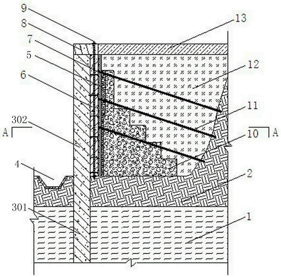
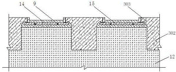
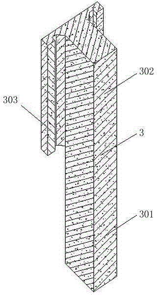
[0039] figure 1 It is a schematic diagram of the high-fill prefabricated cast-in-place combined pile-slab wall protection structure of the present invention, figure 2 It is the construction plan view before the prefabricated soil retaining board 6 of the present invention is not installed, image 3 It is a perspective view of the anti-slide pile in the present invention, Figure 4 It is a perspective view and a schematic connection diagram of a prefabricated earth retaining board in the present invention, Figure 5 It is a perspective view of the cover beam in the present invention, Figure 6 yes figure 1Sectional view along A-A direction.

[0040] refer to Figure 1-6 As shown, the high-fill prefabricated cast-in-place combined ...


PUM


Abstract

The invention relates to a construction method of a high-fill prefabricated cast-in-situ combined pile slab wall protection structure. The construction method comprises the steps of construction preparation, construction of an anti-slide pile, construction of a prefabricated breast board, construction of a prefabricated cover beam, construction of a heat insulating board, installation of a drainage pipe, construction of an oblique breast board anchor cable, construction of a vertical gravel drainage body, construction of a bubble concrete backfill layer, construction of a drainage ditch and the like. According to the construction method of the high-fill prefabricated cast-in-situ combined pile slab wall protection structure, the high-fill prefabricated cast-in-situ combined pile slab wall protection structure is formed by combining the anti-slide pile provided with a connecting wing plate with the breast board, the prefabricated cover beam is installed at the top, the breast board, the anti-slide pile and the cover beam are connected into a whole through the prestressed anchor cable, and thus compared with a traditional high-fill retaining wall, the construction speed is high, the stability of the structure is good, and the safety performance is high. According to the construction method, the construction technique is simple, pile slabs and grouped piles can be constructed synchronously, the construction period is short, and the obtained protection structure has the advantages that the overall stability is good, the adaptability is high, the ant-slide performance is good, and breast boards can be prefabricated in a centralized mode.

Description

technical field [0001] The invention belongs to the field of highway engineering, specifically a high-fill prefabricated cast-in-place combined pile slab suitable for the construction of embankment anti-sliding retaining walls with large terrain height differences in permafrost regions and also suitable for the reinforcement of landslides Construction method of wall protection structure. Background technique [0002] When constructing high-grade highways and high-speed railways in high-cold and permafrost regions, there are two main construction difficulties: one is complex terrain conditions such as cliffs and walls. The foundations of many roadbed projects are directly located on mountains and rocks. The stability of the slope is poor, and it is prone to local deformation such as collapse and slippage, so the embankment retaining wall must be added; second, the foundation in the permafrost area is prone to change, and the frozen soil in the warm season forms a seasonal mel...

Claims


Application Information

Patent Timeline
Patent Type & Authority Applications(China)
IPC IPC(8): E02D29/02
CPCE02D29/02E02D29/0233
Inventor 王新泉
Owner 杭州市交通规划设计研究院有限公司
Why Eureka
Try Eureka