Independent retarder in front of box

A retarder and fixed wheel technology, applied in the direction of brake type, hydraulic resistance brake, mechanical equipment, etc., can solve the problem that the braking effect is not very obvious, and achieve a simple structure, strong applicability and high braking safety. Effect

Inactive Publication Date: 2016-03-23
SHAANXI AEROSPACE POWER HIGH TECH
View PDF7 Cites 3 Cited by
  • Summary
  • Abstract
  • Description
  • Claims
  • Application Information

AI Technical Summary

Problems solved by technology

The braking effect

Method used


Image

  • Independent retarder in front of box
  • Independent retarder in front of box
  • Independent retarder in front of box

Examples


Embodiment Construction

[0020] Due to the excessive braking load of large-tonnage trucks and large passenger cars, there will be thermal decline of the braking performance of the brakes, which will seriously affect the braking safety of the vehicles. Domestic tractors mainly water the brake pads when going downhill. It is not a very obvious problem. The present invention proposes an independent retarder in front of the box, which is installed between the engine and the gearbox to play the role of auxiliary braking.

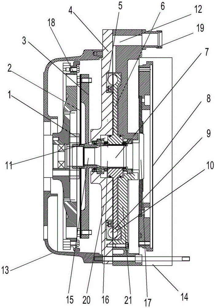
[0021] Attached below figure 1 , figure 2 and image 3 The structure of the present invention is described:

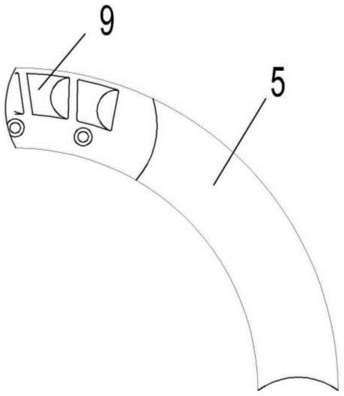
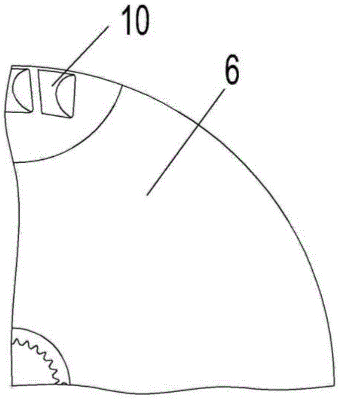
[0022] An independent retarder in front of the box, including a connecting hub 1, a flexible input plate 2, an input disc 3, a retarder housing 4, a retarder fixed wheel 5, a retarder moving wheel 6, an output shaft 7 and a flywheel 8;

[0023] like figure 2 As shown, the fixed wheel 5 of the retarder is an annular structure, and a plurality of first grooves 9 are evenly op...


PUM


Abstract

The invention relates to a retarder, in particular to an independent retarder arranged in front of a box. The independent retarder is mainly used for medium-heavy type vehicles. The independent retarder arranged in front of the box is composed of a connecting hub, a flexible input plate, an input disc, a retarder shell, a retarder fixed wheel, a retarder movable wheel, an output shaft and a flywheel. The retarder is simple in structure, high in braking safety and capable of effectively solving the problems that a water spray brake pad is mainly used for a domestic tractor in the downhill process, and the braking effect is not very obvious.

Description

technical field [0001] The invention relates to a retarder, in particular to an independent retarder in front of the box mainly used in medium and heavy vehicles. Background technique [0002] With the development of vehicles towards high speed and heavy load, relying solely on traditional mechanical friction brakes can no longer meet people's requirements for vehicle safety and comfort, especially in mountainous areas (large-tonnage trucks and large passenger cars). In order to limit the speed of the vehicle when going downhill, it is necessary to ensure continuous braking for a long time. Frequent braking on long and large slopes will cause the brake shoes to heat up, the friction coefficient will decrease, and the braking load will be too large. The braking performance of the brakes will appear. The phenomenon of thermal recession seriously affects the braking safety of the car. Domestic tractors mainly water the brake pads when going downhill. The braking effect is not...

Claims


Application Information

Patent Timeline
IPC IPC(8): F16D57/00
Inventor 严周维刘兴国黄龙李静王宇飞赵紫苓黄显臣
Owner SHAANXI AEROSPACE POWER HIGH TECH
Why Eureka
Try Eureka