Ultra-low temperature ball valve

A technology of ultra-low temperature and ball valves, which is applied in the direction of valve details, valve devices, and valve housing structures, and can solve problems affecting the structural strength of the valve stem, easy blockage of ultra-low temperature ball valves, and reduced service life of the valve stem, so as to increase exhaust efficiency and safety performance, long service life, and the effect of eliminating leakage

Inactive Publication Date: 2016-03-23
DAFENG OKAY FLUID MACHINERY
View PDF0 Cites 7 Cited by
  • Summary
  • Abstract
  • Description
  • Claims
  • Application Information

AI Technical Summary

Problems solved by technology

The pressure relief hole set at the outlet of the ball is generally directly connected with the outlet channel. When the ball is in a closed state, the ultra-low temperature liquid medium in the pipeline will seep into the gap between the ball and the valve seat through the pressure relief hole when passing through the ultra-low temperature ball valve. Between the valve seat and the valve stem, the probability of liquid medium leakage is increased. At the same time, the spare pressure relief hole set in the center of the lower end of the valve stem will directly affect the structural strength of the valve stem. The valve stem is easy to break, which reduces the service life of the valve stem. , In addition, when the number of rotations between the valve stem and the ball is too many, a gap will be generated. At this time, the ball is prone to position deviation when rotating in the valve body, resulting in unstable phenomena such as easy blockage of the ultra-low temperature ball valve and change in the flow direction of the liquid medium.

Method used


Image

  • Ultra-low temperature ball valve
  • Ultra-low temperature ball valve
  • Ultra-low temperature ball valve

Examples


Embodiment Construction

[0010] The specific content of the present invention will be described in detail below in conjunction with the accompanying drawings and specific embodiments.

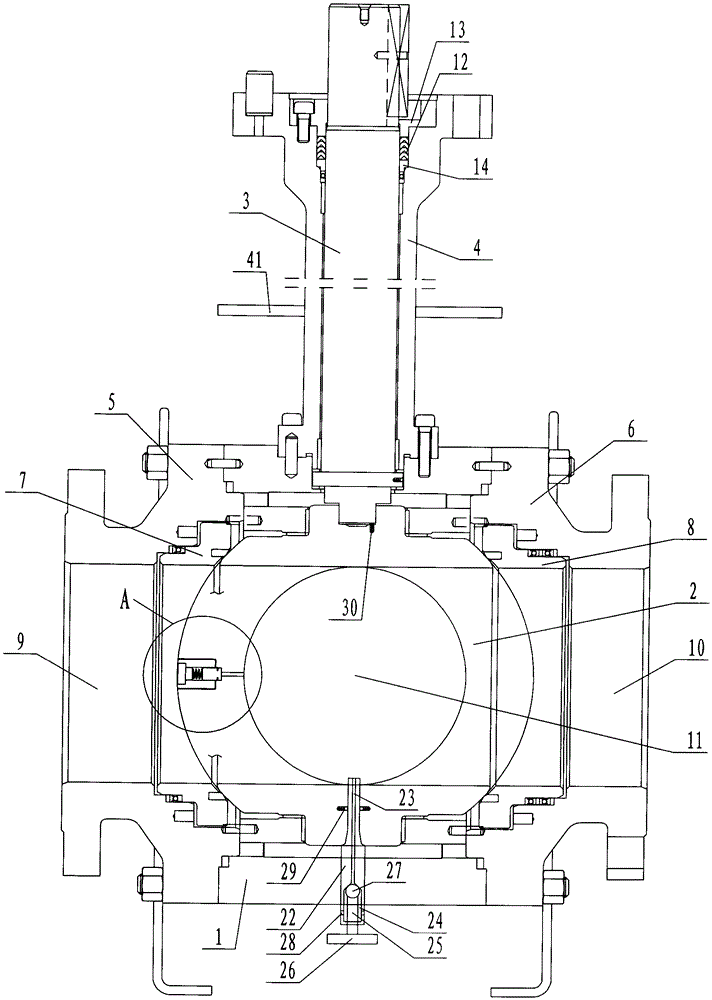
[0011] Such as figure 1 , figure 2 , image 3 As shown, the ultra-low temperature ball valve includes: a valve body 1, a ball 2 arranged in the valve body 1 and a valve stem 3 connected to the upper end of the ball 2, and a long neck cover 4 arranged outside the valve stem 3 at the upper end of the valve body 1. The inlet valve cover 5 and the outlet valve cover 6 on both sides of the valve body 1, the inlet valve seat ring 7 arranged between the inlet valve cover 5 and the ball 2, and the inlet valve seat ring 7 arranged between the outlet valve cover 6 and the ball 2 Between the outlet valve seat ring 8, an inlet channel 9 is provided in the inlet valve cover 5 and the inlet valve seat ring 7, and an outlet is provided in the outlet valve cover 6 and the outlet valve seat ring 8. A channel 10, a cavity channel 11...


PUM


Abstract

The invention discloses an ultra-low temperature ball valve long in service life. The ultra-low temperature ball valve comprises a valve body, a ball arranged in the valve body, a valve rod connected with the upper end of the ball, a long-neck cover, an inlet end valve cover, an outlet end valve cover, an inlet end valve base ring and an outlet end valve base ring. The long-neck cover is arranged on the outer side of the part, at the upper end of the valve body, of the valve rod. The inlet end valve cover and the outlet end valve cover are arranged on the two sides of the valve body. The inlet end valve base ring is arranged between the inlet end valve cover and the ball. The outlet end valve base ring is arranged between the outlet end valve cover and the ball. An inlet channel is arranged in the inlet end valve cover and the inlet end valve base ring. An outlet channel is arranged in the outlet end valve cover and the outlet end valve base ring. A middle cavity channel communicated with the inlet channel and the outlet channel is arranged in the ball. Sealing padding is arranged between the upper end of the long-neck cover and the valve rod. A gland matched with the sealing padding is arranged between the part, at the upper end of the sealing padding, of the long-neck cover and the valve rod.

Description

technical field [0001] The invention relates to a valve, in particular to an ultra-low temperature ball valve. Background technique [0002] At present, ultra-low temperature ball valves are used in pipelines in the electric power, hydraulic, petrochemical, and metallurgical industries to cut off the liquid in the pipeline. The existing ultra-low temperature ball valves generally have pressure relief holes on the inlet side of the ball. Partially set spare pressure relief holes. The pressure relief hole set at the outlet of the ball is generally directly connected with the outlet channel. When the ball is in a closed state, the ultra-low temperature liquid medium in the pipeline will seep into the gap between the ball and the valve seat through the pressure relief hole when passing through the ultra-low temperature ball valve. Between the valve seat and the valve stem, the probability of liquid medium leakage is increased. At the same time, the spare pressure relief hole se...

Claims


Application Information

Patent Timeline
IPC IPC(8): F16K5/06F16K5/12F16K27/12
CPCF16K5/0663F16K5/12F16K27/12
Inventor 朱华炳丁学峰顾云飞李波
Owner DAFENG OKAY FLUID MACHINERY
Why Eureka
Try Eureka