
Biomass gas and carbon co-production boiler

A biomass and boiler technology, applied in the field of boilers, can solve the problems such as the inability of equipment to operate normally, the difficulty in ensuring the quality of fixed carbon, and the bulky and bulky gasifier.

Active Publication Date: 2016-03-23
新乡市工神及第生物质锅炉有限公司 +1
View PDF8 Cites 4 Cited by
  • Summary
  • Abstract
  • Description
  • Claims
  • Application Information

AI Technical Summary

Problems solved by technology

However, due to the large and bulky gasifier and the small gas production capacity, the coal-fired boilers used are limited to boilers with an evaporation capacity of less than 2 tons, and they are mainly hot water boilers
[0003] To realize the biomass steam-charcoal cogeneration boiler, the following technical problems need to be solved. First, the biomass gasifier and the boiler body are two separate installation methods. The combustible gas after the biomass gasifier is gasified needs to be sent into the boiler through the pipeline The main body is burned by a dedicated burner, and the gas is cooled during pipeline transportation, resulting in heat loss. At the same time, the tar in the gas is precipitated and adhered to the pipe wall, which will block the pipeline and cause the equipment to fail to operate normally; secondly, the gasifier adopts It is a solidified bed form, and the fixed carbon after gasification needs to be unloaded manually, which makes it difficult for the equipment to run continuously and smoothly, and the quality of the produced fixed carbon is not easy to guarantee

Method used


Image

  • Biomass gas and carbon co-production boiler
  • Biomass gas and carbon co-production boiler
  • Biomass gas and carbon co-production boiler

Examples


Embodiment Construction

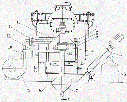
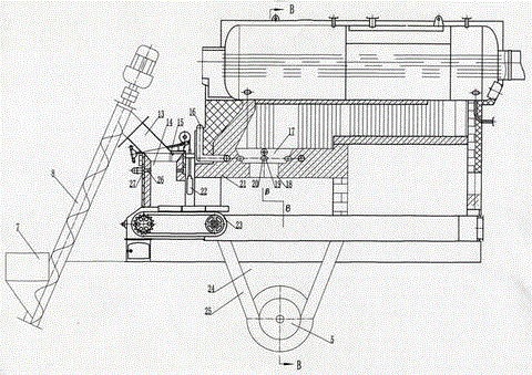
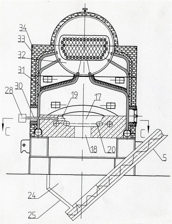
[0011] The biomass steam-charcoal co-production boiler of the present invention can be made by transforming the original coal-fired boiler, or a newly designed biomass steam-charcoal co-production boiler can be adopted. The former uses the original chain grate, boiler heating body and fan, etc., which reduces equipment costs, and is especially suitable for the transformation of coal-fired boilers, while the latter is suitable for new biomass-gas-charcoal co-production boilers.

[0012] The transformation of the coal-fired boiler into a biomass steam-charcoal co-production boiler is described in detail. First, the length of the original chain 23 grate is changed to a specification suitable for the required length, and the body base of the gasification chamber 14 is set on the chain grate. On one end, the gasification chamber body is fixed on the base of the gasification chamber body, the upper part of the gasification chamber is provided with an air gasification agent air inlet ...


PUM


Abstract

The invention provides a biomass gas and carbon co-production boiler. The biomass gas and carbon co-production boiler comprises a vaporizing chamber, a boiler heated chamber and a chain grate, wherein a fuel gas combustion chamber is arranged below the boiler heated chamber, the fuel gas combustion chamber communicates with the boiler heated chamber, and a boiler arch is arranged between the vaporizing chamber and the fuel gas combustion chamber; a fuel gas channel is arranged between the lower end of the boiler arch and the chain grate, and the vaporizing chamber and the fuel gas combustion chamber respectively communicate with the fuel gas channel; the chain grate is arranged below the vaporizing chamber and the boiler arch, a carbon storage chamber is arranged below the fuel gas combustion chamber and the bottom end of the chain grate, a carbon discharging opening is formed in the carbon storage chamber, and the shell of the carbon storage chamber is a water jacket shell; an igniting hole and an air gasifying agent air inlet nozzle are formed in the upper part of the vaporizing chamber, and the air inlet nozzle is connected with a fan through a pipeline; and air distribution pipes are uniformly arranged in the fuel gas combustion chamber, all the air distribution pipes are connected with the fan through air pipes, an igniter and an automatic igniting device are arranged on one side of the combustion chamber, air quantity regulating valves are arranged on the air pipes, and outlets of the air distribution pipes uniformly distributed are in the tangential direction of the inner wall of the fuel gas combustion chamber.

Description

Technical field: [0001] The invention relates to a boiler, in particular to a biomass steam-charcoal co-production boiler. Background technique: [0002] Biomass gasification and biomass boilers were originally separate technologies. With the improvement of national environmental protection requirements, the use of coal-fired boilers with an evaporation capacity of less than 30 tons has been banned. In order to meet the needs of the current conditions, there are cases in the market where biomass gasifiers and coal-fired boilers are used together. However, due to the factors that the gasifier is too bulky and bulky and the gas production is small, the supporting coal-fired boilers are limited to boilers with an evaporation capacity of less than 2 tons, and are mainly hot water boilers. [0003] To realize the biomass steam-charcoal co-production boiler, the following technical problems need to be solved. First, the biomass gasifier and the boiler body are two separate insta...

Claims


Application Information

Patent Timeline
Patent Type & Authority Applications(China)
IPC IPC(8): F23B90/06
CPCF23B90/06
Inventor 孔祥凯孔繁利
Owner 新乡市工神及第生物质锅炉有限公司
Features
  • Generate Ideas
  • Intellectual Property
  • Life Sciences
  • Materials
  • Tech Scout
  • Unparalleled Data Quality
  • Higher Quality Content
  • 60% Fewer Hallucinations
Learn More