Low light level imaging detector

A low-light imaging and detector technology, applied in the field of detectors, can solve the problems of complicated manufacturing process and large number of optical components, and achieve the effects of ensuring the quality of the preparation, improving the efficiency of the preparation, and reducing the difficulty of the preparation process

Inactive Publication Date: 2016-03-23
CHANGCHUN INST OF OPTICS FINE MECHANICS & PHYSICS CHINESE ACAD OF SCI
View PDF4 Cites 9 Cited by
  • Summary
  • Abstract
  • Description
  • Claims
  • Application Information

AI Technical Summary

Problems solved by technology

[0005] In view of this, the object of the present invention is to provide a low-light imaging detector with miniaturization, large field of view, and high sen

Method used


Image

  • Low light level imaging detector

Examples


Embodiment 1

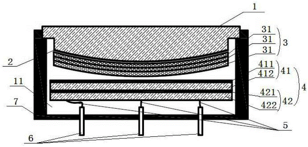
[0041] like figure 1 As shown, a low-light imaging detector includes: a housing 7, an input window 1, a photocathode layer 2, a microchannel plate image intensifier 3, an inductively encoded anode 4, a vacuum electrode 6 and an electrode lead 5, wherein the input The window 1, the vacuum electrode 6 and the metal shell 7 form a closed high-vacuum environment, which ensures that the detector can work normally in the atmosphere or space environment, and has good electromagnetic compatibility characteristics. The photocathode layer 2, microchannel The plate image intensifier 3, the induction coding anode 4 and the anode lead 5 are all placed in a high vacuum environment.

[0042] The outer surface of the above-mentioned input window 1 is a plane, the inner surface is an aspherical surface, and the thickness of the input window is more than 1.5 mm to ensure the strength of the input window; the material of the input window is fused silica, so that ultraviolet to near-infrared radi...


PUM


Abstract

The invention provides a low light level imaging detector. The detector comprises a casing (7), an input window (1), a photoelectric cathode layer (2), a micro-channel-plate image enhancer (3), an inductive coding anode (4), vacuum electrodes (6) and electrode leads (5), wherein the input window (1) and the metal casing (7) form an enclosed high-vacuum environment, and the photoelectric cathode layer (2), the micro-channel-plate image enhancer (3), the inductive coding anode (4) and the electrode leads (5) are all arranged in the high-vacuum environment. The low light level imaging detector can effectively reduce the aberration of a detection image, reduce the amount of used optical components and improve the imaging quality, and also has the advantages of simple structure, reasonable design, simple preparation process, high preparation efficiency and high quality.

Description

technical field [0001] The invention relates to the field of detectors, and in particular provides a low-light imaging detector, which is suitable for cosmic space environment and atmospheric environment under normal pressure, and can be applied to early warning of solar blindness, space astronomical observation, high-voltage discharge detection, fire detection and the like. Background technique [0002] Low-light imaging detectors are widely used in scientific research and national defense construction. For low-light imaging optical instruments for space, national defense and scientific applications, it is necessary to use fewer optical elements, obtain a large field of view and obtain a large system transmission efficiency in order to reduce the volume and weight of the instrument and expand the field of view of the instrument , to improve the imaging quality of the instrument. [0003] However, the previous low-light imaging detectors have problems such as a large number...

Claims


Application Information

Patent Timeline
IPC IPC(8): G01J1/42G01J1/02G01J1/04
CPCG01J1/0271G01J1/0407G01J1/42G01J2001/0276
Inventor 陈波张宏吉
Owner CHANGCHUN INST OF OPTICS FINE MECHANICS & PHYSICS CHINESE ACAD OF SCI
Why Eureka
Try Eureka