
Coaxial pathway testing device of base

A technology of access test and base, applied in the direction of measurement device, measurement of electricity, measurement of electric variables, etc., can solve the problems of complicated test process, time-consuming and labor-intensive, etc., and achieve the effect of simple test process, saving labor and time

Active Publication Date: 2016-03-23
SHENXUN COMP KUNSHAN
View PDF9 Cites 2 Cited by
  • Summary
  • Abstract
  • Description
  • Claims
  • Application Information

AI Technical Summary

Problems solved by technology

[0011] Therefore, the purpose of the present invention is to provide a coaxial path testing device for the base, to solve the problems of complex testing process, time-consuming and manpower-consuming when testing the coaxial path of the base in the prior art

Method used


Image

  • Coaxial pathway testing device of base
  • Coaxial pathway testing device of base
  • Coaxial pathway testing device of base

Examples


Embodiment Construction

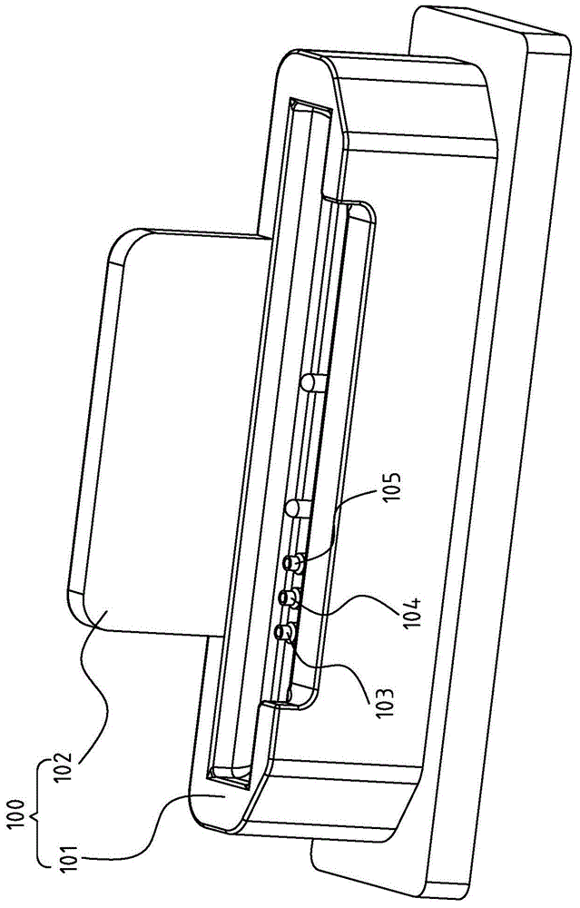
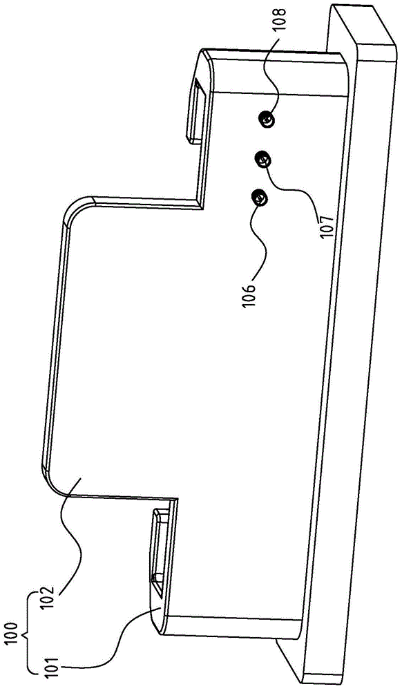
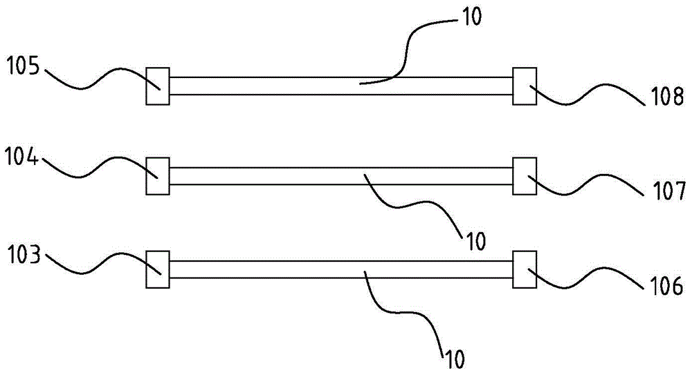
[0030] Please refer to Figure 6 , Figure 7 , Figure 6 Shown as a schematic structural view of a preferred embodiment of the coaxial path testing device of the base of the present invention, Figure 7 It is a schematic diagram of the circuit structure of a preferred embodiment of the coaxial path testing device of the base of the present invention, Figure 8 It is a schematic diagram of the structure of the shorting joint of a preferred embodiment of the coaxial path testing device of the base of the present invention.

[0031] In order to achieve the above object, the present invention provides a coaxial path testing device for the base, the base 100 (please refer to figure 1 , figure 2 , may include a base plate 101 and a back plate 102) having first coaxial interfaces 103, 104, 105 connected to the coaxial interface of the electronic product and connecting with the first coaxial interfaces 103, 104, 105 through the coaxial line 10 (please refer to the image 3 , ...


PUM


Abstract

The invention discloses a coaxial pathway testing device of a base. The base is provided with first coaxial interfaces connected with machine coaxial interfaces of electronic products and second coaxial interfaces connected with the first coaxial interfaces through coaxial lines. The device comprises test fixtures and short circuit connectors; the fixtures are provided with fixture coaxial interfaces correspondingly connected with the first coaxial interfaces, and each test fixture is further provided with a power supply, which is in series connection with the fixture coaxial interfaces, and display units; and the short circuit connectors are in detachable connection with the second coaxial interfaces, and inner pins and outer ring pins of the second coaxial interfaces are in short connection. The short circuit connectors only need to be installed and detached, and then a test purpose can be achieved through a determination display unit, so the test process is simple, only needs one person, and saves manpower and time.

Description

【Technical field】 [0001] The invention relates to a test device, in particular to a coaxial path test device for a base. 【Background technique】 [0002] Some current electronic products are placed using a docking base to facilitate viewing by users. For docking for handheld electronic products or tablet computers, it usually has two main functions. First, as a stand for electronic products, it can be used without holding hands when the user is working; second, it can be used as a switch for charging or data transmission of electronic products. [0003] Please refer to figure 1 , figure 2 , figure 1 A schematic diagram of the front structure of the base of an electronic product shown in the prior art, figure 2 It is a schematic diagram of the back structure of a base of an electronic product in the prior art. The base 100 includes a base plate 101 and a back plate 102, the base plate 101 has three first coaxial interfaces 103, 104, 105 (pogo interfaces), and the side ...

Claims


Application Information

Patent Timeline
IPC IPC(8): G01R31/02
Inventor 沈细荣
Owner SHENXUN COMP KUNSHAN
Features
  • Generate Ideas
  • Intellectual Property
  • Life Sciences
  • Materials
  • Tech Scout
  • Unparalleled Data Quality
  • Higher Quality Content
  • 60% Fewer Hallucinations
Learn More