LED synchronous rectifying circuit

A technology of LED circuit and synchronous rectification, which is applied in the direction of electric light source, electrical components, electroluminescent light source, etc., can solve the problems of low photoelectric conversion efficiency of LED, decrease of LED efficiency, large heat generation of LED, etc., so as to prolong life and reduce heat , the effect of improving efficiency

Inactive Publication Date: 2016-03-23
WUHU RUIXIN ELECTRONICS TECH CO LTD
View PDF6 Cites 0 Cited by
  • Summary
  • Abstract
  • Description
  • Claims
  • Application Information

AI Technical Summary

Problems solved by technology

However, since the photoelectric conversion efficiency of LEDs is still relatively low at present, in high-power LED lamps, the heat generated by LEDs is large and the temperature is relatively high.
When the LED works at high temperature, the efficiency of the LED decreases and the lifespan is shortened. In addition, due to the high heat generation of the LED, high requirements are placed on the heat dissipation design of the LED lamp.

Method used


Image

  • LED synchronous rectifying circuit
  • LED synchronous rectifying circuit

Examples


Embodiment Construction

[0015] Preferred embodiments of the present invention will be described in detail below.

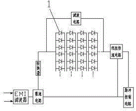
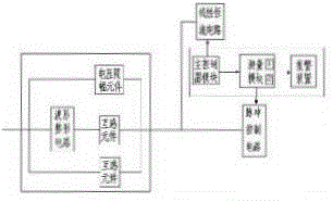
[0016] A LED synchronous rectification circuit, comprising an EMI filter, a rectification circuit, a converter, an LED circuit and a pulse control circuit, the output end of the EMI filter is connected to the rectification circuit, and the outlets of the rectification circuit are respectively connected to the converter and the The pulse control circuit is connected, the converter is connected in series with the LED circuit, the LED circuit is connected in series by several LED lamp groups, the LED lamp group is connected in parallel by several diodes, and a linear constant current is connected in series at the end of the LED circuit circuit, the linear constant current circuit is connected between the rectification circuit and the pulse control circuit.

[0017] Among them, the function of the EMI filter is to allow the frequency signal when the equipment is working normally to enter the...


PUM


Abstract

The present invention discloses an LED synchronous rectifying circuit, and relates to the field of LED lamps. The LED synchronous rectifying circuit comprises an EMI filter, a rectifying circuit, a converter, an LED circuit and a pulse control circuit, wherein an output end of the EMI filter is connected to the rectifying circuit; an outlet end of the rectifying circuit is separately connected with the converter and the pulse control circuit; the converter is connected in series with the LED circuit; the LED circuit is formed by connecting a plurality of LED lamp banks in series; each LED lamp bank is formed by connecting a plurality of diodes in parallel; and a linear constant-current circuit is connected in series to the tail end of the LED circuit and is connected between the rectifying circuit and the pulse control circuit. According to the LED synchronous rectifying circuit disclosed by the present invention, a current flowing through the LED lamp banks is in a pulse form to control each LED lamp bank to be sequentially conducted for emitting light and turned off, so that the current time of LEDs in unit time can be effectively shortened, heat generated by the LEDs is reduced, efficiency of the LEDs is improved, and the service life of the LEDs is prolonged.

Description

technical field [0001] The invention relates to the field of LED lamps, in particular to an LED synchronous rectification circuit. Background technique [0002] With its advantages of high efficiency, energy saving, environmental protection, long life and high reliability, LED is gradually replacing traditional incandescent lamps and fluorescent lamps as a new generation of lighting sources. Since LED is a semiconductor device, LED must be powered to work stably and reliably. At present, the LED drive power supply on the market is mainly a PWM modulated constant current drive power supply, and the current flowing through the LED is a constant direct current. However, since the photoelectric conversion efficiency of LEDs is relatively low at present, in high-power LED lamps, the heat generated by LEDs is very large and the temperature is relatively high. When the LED works at high temperature, the efficiency of the LED decreases and the lifespan is shortened. In addition, ...

Claims


Application Information

Patent Timeline
Patent Type & Authority Applications(China)
IPC IPC(8): H05B33/08H02M7/217H05B44/00
CPCY02B20/30
Inventor 崔俊国朱成华
Owner WUHU RUIXIN ELECTRONICS TECH CO LTD
Why Eureka
Try Eureka