
Tool for machine-cutting a workpiece

A technology of cutting and tooling, which is applied in the field of tools for cutting workpieces, can solve problems such as damage, insufficient removal of chips, and reduced service life of tools, and achieve easy work, high load capacity, and improved service life. Effect

Inactive Publication Date: 2016-03-23
KWB GERMANY
View PDF9 Cites 1 Cited by
  • Summary
  • Abstract
  • Description
  • Claims
  • Application Information

AI Technical Summary

Problems solved by technology

The resulting increased mechanical load on the tool and the resulting temperature rise, in particular on the toothing of the tool, lead to a reduced service life of the tool and also make it susceptible to functional failures
[0005] In known tools of this type, due to insufficient conduction of the chips in the region of the toothing, too rapid removal of the toothing profile and damage and fracture of the individual teeth of the toothing often occur.

Method used


Image

  • Tool for machine-cutting a workpiece
  • Tool for machine-cutting a workpiece
  • Tool for machine-cutting a workpiece

Examples


Embodiment Construction

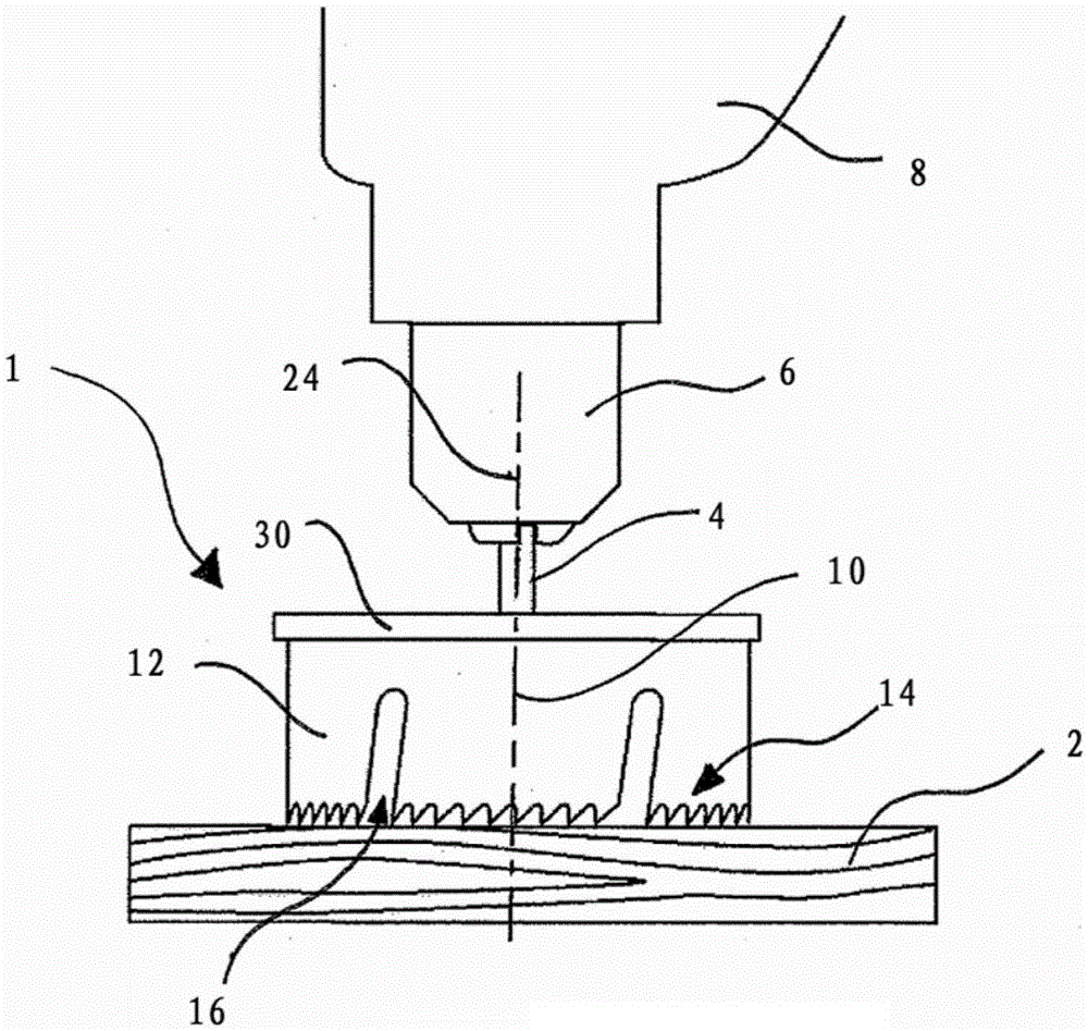
[0027] According to figure 1 In the exemplary embodiment shown, the tool 1 is clamped in the rotationally driven tool spindle 6 of the machine tool 8 , so that the non-positive and / or The form-fitting connection makes it possible to transmit the rotational movement of the tool spindle 6 to the tool 1 .

[0028] In this case, the tool center axis 10 coincides with the axis of rotation 24 of the rotationally driven tool spindle 6 . The fastening means 4 is also connected to a carrier element 30 , into which the tool housing is in turn locked in a rotationally fixed manner at least in the direction of rotation.

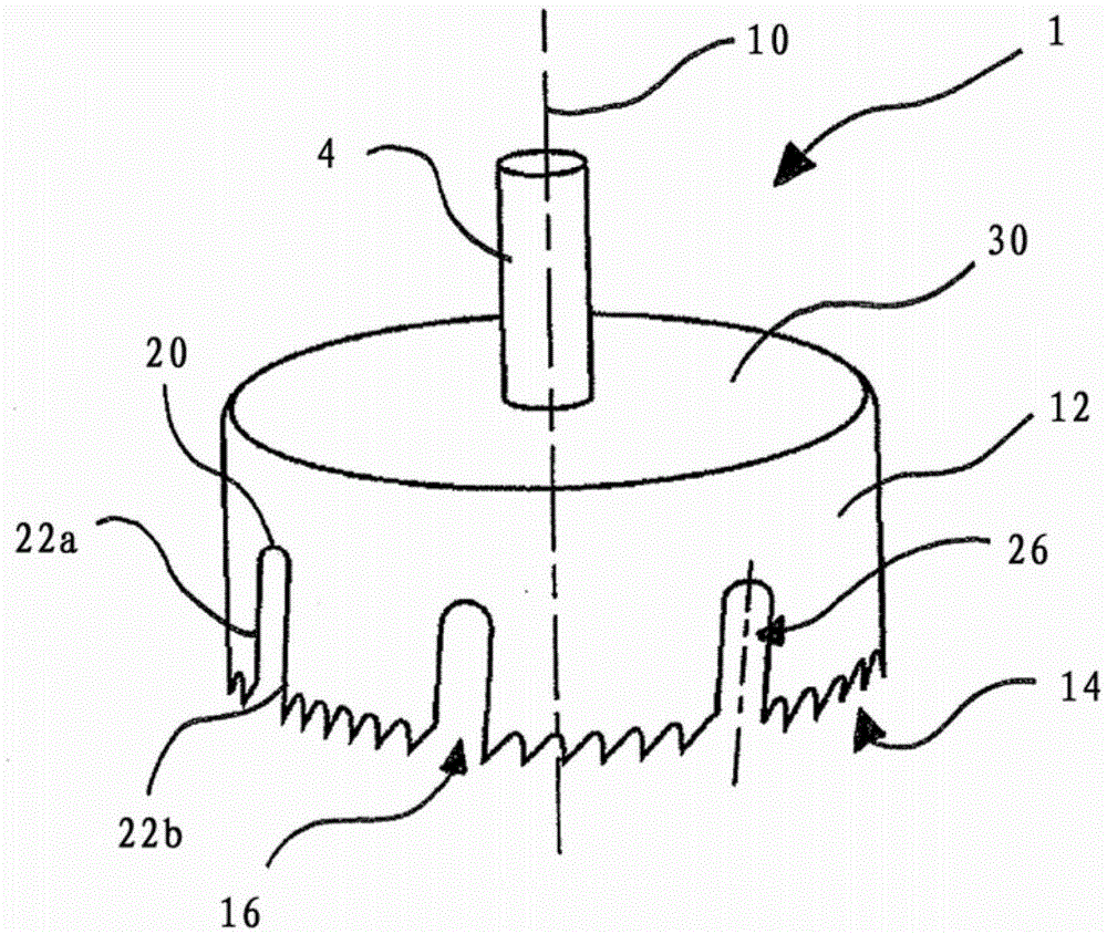
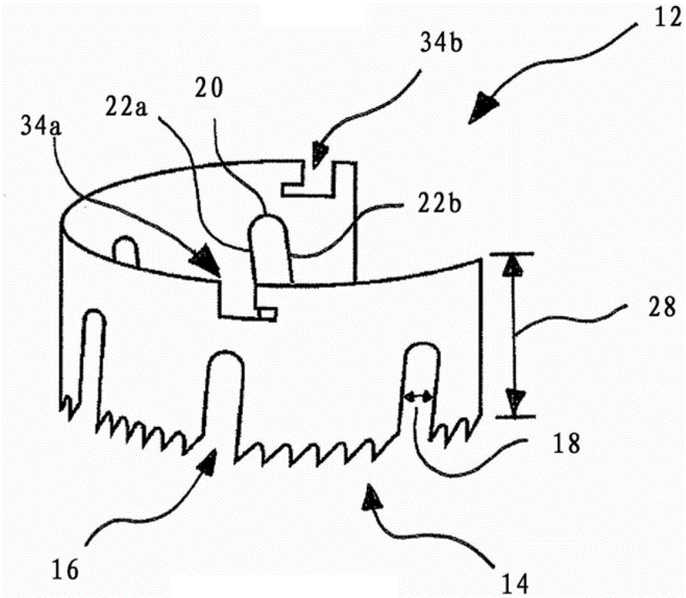
[0029] A toothing 14 is provided on the side of the tool housing 12 facing away from the support element 30 and the fastening means 4 . The toothing 14 and the tool housing 12 have a recess 16 which extends from the toothing 14 up to more than half the height of the tool housing.

[0030] The toothing 14 interrupted by the recess 16 is in contact with the workpiece 2 ...


PUM


Abstract

The invention relates to a tool (1) for machine-cutting a workpiece (2), having a fastening means (4) for fastening the tool (1) in a rotatably driven tool spindle (6) of a machine tool (8), a tool casing (12), which runs at least partially around a tool centre axis (10), and a set of teeth (14), which runs at least partially around the tool centre axis (10) and is arranged on the side of the tool casing (12) that faces away from the fastening means (4). According to the invention, the tool (1) has at least one, preferably a plurality of recesses (16), which extend from the set of teeth (14) into the tool casing (12).

Description

technical field [0001] The invention relates to a tool for cutting a workpiece, which has: a fastening mechanism for fastening the tool in a rotationally driven tool spindle of a machine tool; a tool housing at least partially surrounding a central axis of the tool; and a toothing at least partially surrounding the tool center axis, which is arranged on the side of the tool housing facing away from the fastening means. Background technique [0002] Use this tool to create large-diameter holes in sheet metal, drywall, or wood. In this case, the diameter of such a large-bore hole is sufficient to realize a line or cable lead-through or recess for sockets or light switches and distribution boxes. [0003] Via the fastening means, the rotational movement of the tool spindle is transmitted to the tool housing and the toothing, so that a hole with the diameter of the surrounding toothing can be introduced into the workpiece to be machined. The maximum depth of the workpiece to b...

Claims


Application Information

Patent Timeline
Patent Type & Authority Applications(China)
IPC IPC(8): B23B51/04
CPCB23B2260/072B23B51/04
Inventor 格里特·布兰德托尔斯滕·伯切尔
Owner KWB GERMANY
Learn More