Closure device

An occluder and occlusion disc technology, applied in the field of medical devices, can solve the problems of embolism, the inability of the first occlusion disc to fit completely with the tissue wall, and the change of blood flow rate, so as to avoid residual shunt and reduce biological risks. , Strengthen the blocking effect

Active Publication Date: 2016-03-30
LIFETECH SCIENTIFIC (SHENZHEN) CO LTD
View PDF5 Cites 9 Cited by
  • Summary
  • Abstract
  • Description
  • Claims
  • Application Information

AI Technical Summary

Problems solved by technology

If the radial dimension of the waist 13 of the occluder is large, or the flexibility of the waist 13 is poor, it is difficult for the waist 13 to deform autonomously according to the shape of the PFO channel, and it is easy to cause the first occlusion disc 11 and / or the second occluder to deform. The blocking disk 12 cannot be completely attached to the tissue wall, so a gap is formed between the disk surface and the tissue wall, which becomes a channel for residual shunt
For small residual shunts, the defect 2 may still eventually occlude as the endothelial cells gradually grow; however, for larger residual shunts, blood flow through the defect 2 will cause changes in blood flow velocity, which can induce thrombosis For this reason, patients need to prolong the time of anticoagulation therapy. If the formed thrombus enters the blood circulation, it may also cause serious adverse events such as embolism.

Method used


Image

  • Closure device
  • Closure device
  • Closure device

Examples


no. 1 example

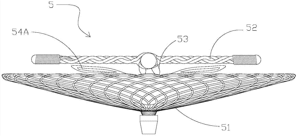
[0065] see figure 2 According to the first embodiment of the present invention, the occluder 5 includes a first occlusion disk 51, a second occlusion disk 52, and an The waist 53 of the blocking disk 51 and the second blocking disk 52; the occluder 5 also includes a plurality of fluffy petal-shaped silk bundles located on the disk surface of the first blocking disk 51 near the waist 53 and near the waist 53 Structure 54A. It should be known that in this embodiment, the wire bundle structure 54 is provided on the first blocking disk 51 for example only, and is not a limitation to the present invention. For example, the wire bundle structure 54 can also be arranged on the second blocking disk 52 on, and close to the waist 53; or the wire bundle structure 54 can be set on the first occlusion disk 51 and the second occlusion disk 52 at the same time.

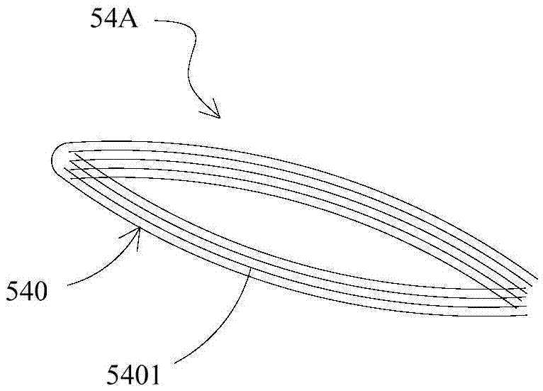
[0066] see image 3 Each petal-shaped wire bundle structure 54A is wound from at least one wire bundle 540 , for example, woun...

no. 2 example

[0085] Figure 12 A schematic diagram of the occluder 5 according to the second embodiment of the present invention is shown, which is different from the first embodiment in that the occluder 5 includes a plurality of braided wire bundle structures 54B arranged around the waist 53 . see Figure 13 , each braided wire bundle structure 54B includes a plurality of intertwined and braided wire bundles 540 , and at least one wire bundle 540 includes a plurality of wires 5401 loosely distributed. Each braided wire bundle structure 54B includes a connected connecting section 543a and a suspended section 543b in the axial direction. dangling.

[0086] The multi-strand wire bundles 540 in the connecting section 543a are intertwined and braided together, for example, may be loosely intertwined and braided together. The suspended section 543b includes a multi-strand wire bundle 540, which can all be the multi-strand wire bundle 540 from the connecting section 543a, that is, the connec...

no. 3 example

[0091] At least one end of the wire bundle structure in the first embodiment and the second embodiment is free to hang in the air. The difference is that in the third embodiment, the wire bundle structure is loosely wound on the disk surface on which it is set, such as the first The blocking disk faces the disk surface of the second blocking disk.

[0092] see Figure 16 with Figure 17 The wire bundle structure 84 of the occluder 8 includes at least one wire, the wire 841 is wound around at least a part of the braided wire 811 of the first occlusion disc 81, for example, the at least one braided wire 811 can be repeatedly wound multiple times to form a fluffy Silk harness structure. Alternatively, at least one wire 841 may be inserted through the plurality of grids 812 formed by the braided wire 811 , for example, repeatedly inserted through multiple times, so as to form a fluffy wire bundle structure. Or, after at least one silk thread 841 is wound around at least one bra...


PUM


Abstract

The invention discloses a closure device. The closure device comprises a first closure disc, a second closure disc, a waist part connected with the first closure disc and the second closure disc and at least one fluffy silk thread bundle structure, wherein the silk thread bundle structures are arranged on at least one of the two opposite disc faces of the first closure disc and the second closure disc and are close to the waist part. As the silk thread bundle structures are arranged adjacent to the waist part, the closure device can stop a damaged opening after being implanted, so that blood flow can be effectively stopped from flowing into the damaged opening from one side of the damaged opening and/or flowing into the other side of the damaged opening from one side of the damaged opening through the damaged opening, and residual bypass flow is avoided. In addition, the silk thread bundle structures are of a fluffy structure, the gap space in the silk thread bundle structures is filled with the blood flow flown in easily to form a seal structure, blood detained in the fluffy structure is prone to thrombus formation, the seal structure can be compacted further, the function of stopping the blood flow is enhanced, extra closure materials are not needed, and the biological risk after implantation is reduced.

Description

technical field [0001] The present invention relates to a medical instrument, in particular to an instrument for occluding passages, defects or openings in the human body, which can be applied to occluders for patent foramen ovale (PFO), and can also be used to occlude patent ductus arteriosus, Atrial septal defect, ventricular septal defect, etc. Background technique [0002] With the continuous development of interventional devices and interventional cardiology, transcatheter interventional occluder minimally invasive treatment of atrial septal defect, ventricular septal defect, patent ductus arteriosus and patent foramen ovale and other congenital heart diseases has become an important method. Endovascular occlusion with interventional methods is also a widely accepted treatment. [0003] see figure 1 , the existing occluder 1 usually includes a first occlusion disk 11, a second occlusion disk 12, and a waist 13 connecting the first occlusion disk 11 and the second occl...

Claims


Application Information

Patent Timeline
Patent Type & Authority Applications(China)
IPC IPC(8): A61B17/00A61B17/12
CPCA61B17/0057A61B17/12109A61B17/12145A61B17/1215A61B2017/00575A61B2017/00592A61B2017/00243A61B2017/00606A61B2017/00623A61B2017/00676A61B17/12177A61B2017/00867
Inventor 庄少春陈文俊
Owner LIFETECH SCIENTIFIC (SHENZHEN) CO LTD
Why Eureka
Try Eureka